Pressure sensor and device for measuring pressure

a pressure sensor and pressure sensor technology, applied in the direction of fluid pressure measurement by mechanical elements, instruments, force measurement, etc., can solve the problems of low yield of sufficiently accurate pressure sensors, limitation of the size reduction of permanent magnets, and the dependence of pressure detection accuracy, etc., to achieve easy production, high manufacturing accuracy, and low manufacturing cost

Inactive Publication Date: 2007-09-06
CENTRAL RESEARCH INSTITUTE OF ELECTRIC POWER INDUSTRY
View PDF4 Cites 10 Cited by
  • Summary
  • Abstract
  • Description
  • Claims
  • Application Information

AI Technical Summary

Benefits of technology

[0018] According to the invention of (5) above, the elastic member layer is made of polyurethane. With this, an effect can be achieved such that a sensor with high manufacturing accuracy can be easily produced with low manufacturing cost.
[0019] According to the invention of (6) above, the coil layer, the elastic member layer, and the metal layer have flexibility applicable to a measurement target or a mounting target. With this, an effect can be achieved such that, surface pressure can be accurately measured even when the surface of a measurement target or a mounting target has a curved shape.
[0020] According to the invention of (7) above, the pressure measuring device includes a pressure sensor formed by laminating a coil layer including a plurality of exciting coils arranged in an array; an elastic member layer made of a non-metal material provided adjacently to the coil layer; and a metal layer made of a metal film provided adjacently to the elastic member layer, and a voltage applying unit that applies a voltage to each exciting coil of the pressure sensor with predetermined time differences. Therefore, various pressure targets can be supported, and pressure can be accurately measured. Also, an effect can be achieved such that excitation of the exciting coils arranged in an array is subjected to excitation control, thereby providing a pressure measuring devic...

Problems solved by technology

However, the technology disclosed in Patent Document 1 has a problem in which pressure detection accuracy depends to a large degree on the quality of the elastic member containing the metal powders.
Therefore there is a problem of low yields of sufficiently accurate pressure sensors.
The technology disclosed in Patent Document 2 has a problem in limitation of size reduction of the permanent ma...

Method used


Image

  • Pressure sensor and device for measuring pressure
  • Pressure sensor and device for measuring pressure
  • Pressure sensor and device for measuring pressure

Examples


first embodiment

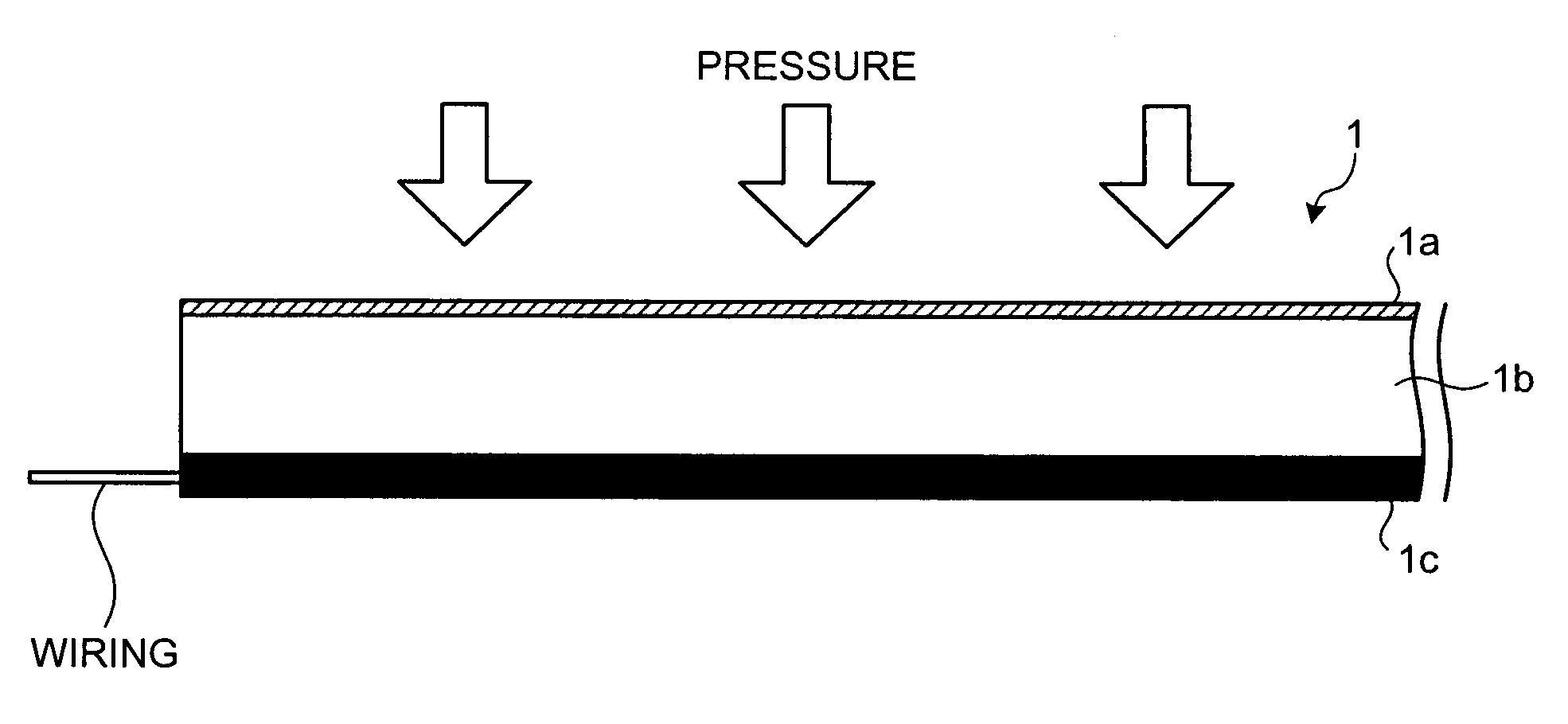
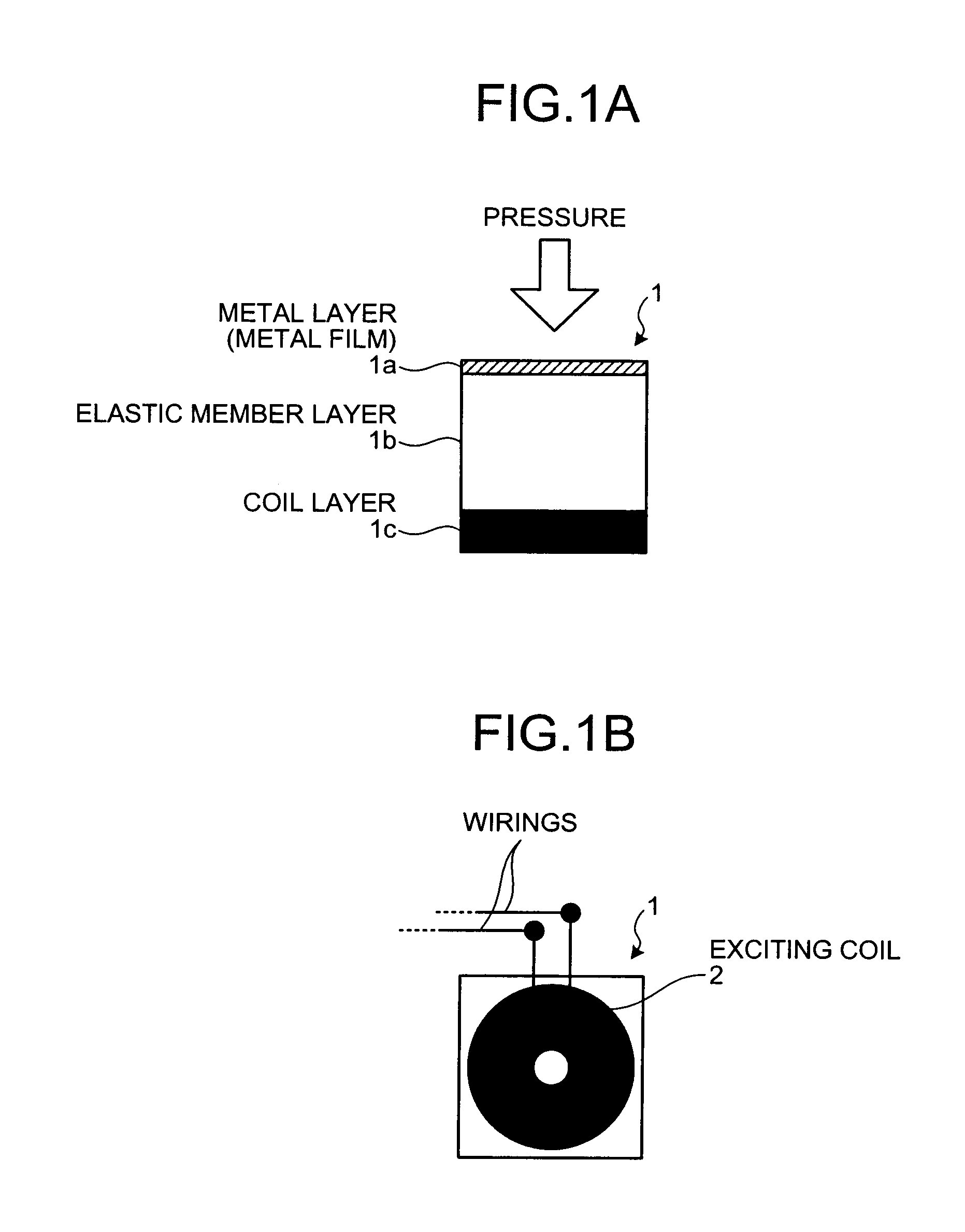
[0036] First, the configuration of the pressure sensor according to the first embodiment will be described. FIG. 1 is a drawing depicting the configuration of the pressure sensor of the first embodiment. FIG. 1A is a side view of a pressure sensor 1, and FIG. 1B is a top view of the pressure sensor 1. In FIG. 1B, a metal layer 1a and an elastic member layer 1b are omitted.

[0037] As depicted in FIG. 1A, the pressure sensor 1 is formed by laminating a metal layer made of a metal film, an elastic member layer made of a non-metal material, such as polyurethane, and a coil layer including an exciting coil.

[0038] Also, as depicted in FIG. 1B, a coil layer 1c of the pressure sensor 1 is provided with an exciting coil 2 and wirings connected to each end of this exciting coil 2. For such wirings, a printed board is used for example. With the exciting coil 2 being interposed between a layer of the printed board connected to one end of the exciting coil 2 and another layer of the printed boa...

second embodiment

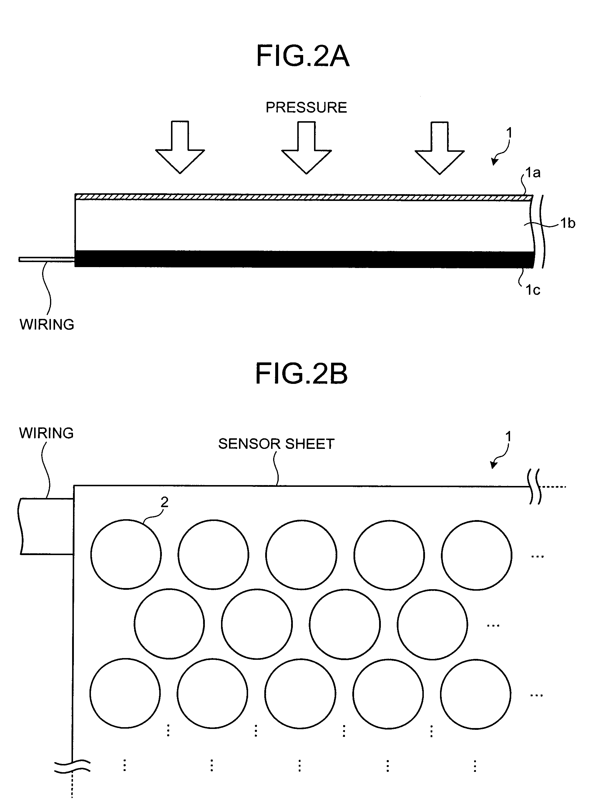
[0057] First, the configuration of the pressure measuring device 10 using the sensor sheet 1 depicted in the first embodiment will be described by using FIG. 6. FIG. 6 is a block diagram of the configuration of the pressure measuring device 10 according to the second embodiment. As depicted in the drawing, the pressure measuring device 10 includes the sensor sheet 1, a power supplying unit 11, a voltage applying unit 12, a detecting unit 13, a displaying unit 14, a storage unit 15, and a controlling unit 16. Also, the storage unit 15 has sensor control information 15a stored therein, and the controlling unit 16 further includes a sensor controlling unit 16a and an analyzing unit 16b.

[0058] The sensor sheet 1 is as depicted in the first embodiment described above. This sensor sheet 1 is connected to the voltage applying unit 12 and the detecting unit 13 via the wirings described above (refer to FIG. 2). The power supplying unit 11 is a device that supplies power for activating the p...


PUM


Abstract

A pressure sensor and a pressure measuring device are provided applicable to a variety of pressure detection targets and capable of measuring a surface pressure. The pressure sensor is configured by laminating a metal layer made of a metal film, an elastic member layer made of a non-metal material, and a coil layer including an exciting coil. Also, as for a sensor sheet on which sensors that each measure point pressure are arranged in an array, variable elements of the elastic member layer and the coil layer are appropriately changed, thereby forming sensors with a single sheet that are different in pressure detection accuracy or pressure detection range for predetermined areas. Also provided is a pressure measuring device that controls exciting timing or frequency of applied voltage of each exciting coil on a sensor sheet.

Description

BACKGROUND OF THE INVENTION [0001] 1. Field of the Invention [0002] The present invention relates to pressure sensors and devices for measuring pressure, and, more particularly, to a pressure sensor and a device for measuring pressure using this pressure sensor capable of flexibly supporting the shape or size of a mounting target or a pressure detection target and also capable of accurately detecting surface pressure of a pressure detection target. [0003] 2. Description of the Related Art [0004] Conventionally, pressure sensors that detect pressure by converting applied pressure to an electrical signal have been known. Some of such pressure sensors detect pressure by using an elastic member such as a rubber as a component therein, utilizing the deformation of the elastic member by pressure. [0005] For example, Patent Document 1 (Japanese Patent Application Laid-Open Publication No. 10-318865) discloses a pressure sensor in which an elastic member containing metal powders admixed the...

Claims


Application Information

Patent Timeline
IPC IPC(8): G01L9/10
CPCG01L1/14
Inventor FUKUTOMI, HIROYUKIOGATA, TAKASHI
Owner CENTRAL RESEARCH INSTITUTE OF ELECTRIC POWER INDUSTRY
Why Eureka
Try Eureka