Lead-free projectile

a projectile and lead-free technology, applied in the field of lead-free projectiles, can solve the problems of not having the required high final ballistic energy required by marksmen, not having the toxic effect, and still present in the target area of ammunition, so as to reduce ricochets, improve the connection to the cartridge sleeve, and reduce the effect of ricochets

Active Publication Date: 2007-09-06
RUAG AMMOTEC GMBH
View PDF18 Cites 46 Cited by
  • Summary
  • Abstract
  • Description
  • Claims
  • Application Information

AI Technical Summary

Benefits of technology

[0016] Use of identical materials for the outer jacket and the jacket core have proved to be very economical and also expedient with regard to density, assembly and thermal expansion.
[0017] A constriction having an outer jacket with a circumferential peripheral constriction on which the front end of a cartridge sleeve is flanged improves the connection to the cartridge sleeve and allows the simple assembly thereof.
[0018] A thickening of the jacket in its front region can reduce ricochets during acute angle firing at hard targets and also serves to determine the center of gravity.

Problems solved by technology

This ammunition, however, does not have the required high final ballistic energy required by marksmen, which is necessary for penetrating armour plating.
A further drawback is the large amount of hard lead (98% Pb+2% Sn) in the core, which has a toxic effect on the environment both in blank ammunition and live ammunition and therefore is undesirable nowadays or even prohibited in some countries.
Thus the escape of heavy metals and / or vapor when firing is prevented; a toxic effect is, however, still present in the target area.
Additionally, the manufacture of such a projectile is costly and too expensive for mass use (infantry ammunition).
The penetrative action of this projectile on armor plated targets is good; the target accuracy thereof is, however, markedly reduced.
In particular with an oblique impact on the target, the front part of the projectile jacket splinters and deforms and thereby presses the hard core out of its initial symmetrical axial position which, as the effective cross-section becomes greater, at least reduces the penetration performance or even leads to ricochets.
Additionally, the manufacture of the projectile is costly and, due to the more or less free positioning of the hard core, may not be carried out with great accuracy.

Method used


Image

  • Lead-free projectile
  • Lead-free projectile
  • Lead-free projectile

Examples


Embodiment Construction

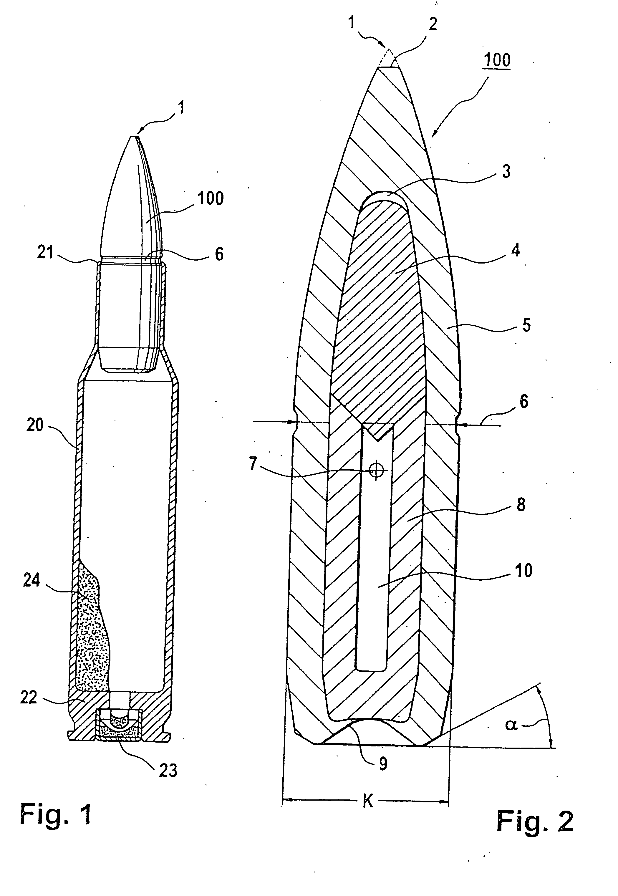
[0028] The tip of a projectile 100 is denoted in FIG. 1 by 1. A flange 21 is inserted into the reduced diameter of a peripheral constriction 6, and which is a component of a cartridge 20 known per se. A standard explosive 24 is located in the cartridge 20, which acts as a propellant for the projectile 100. An impact fuse 23 (SINTOX, trademark of the firm RUAG Ammotec GmbH, Fürth, DE) is inserted in a base 22 of the cartridge 20.

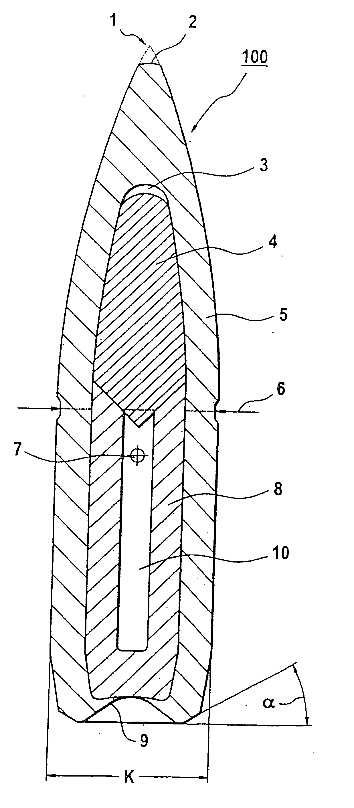
[0029] The preferred rotationally symmetrical projectile 100 is shown in FIG. 2 in an enlarged sectional view.

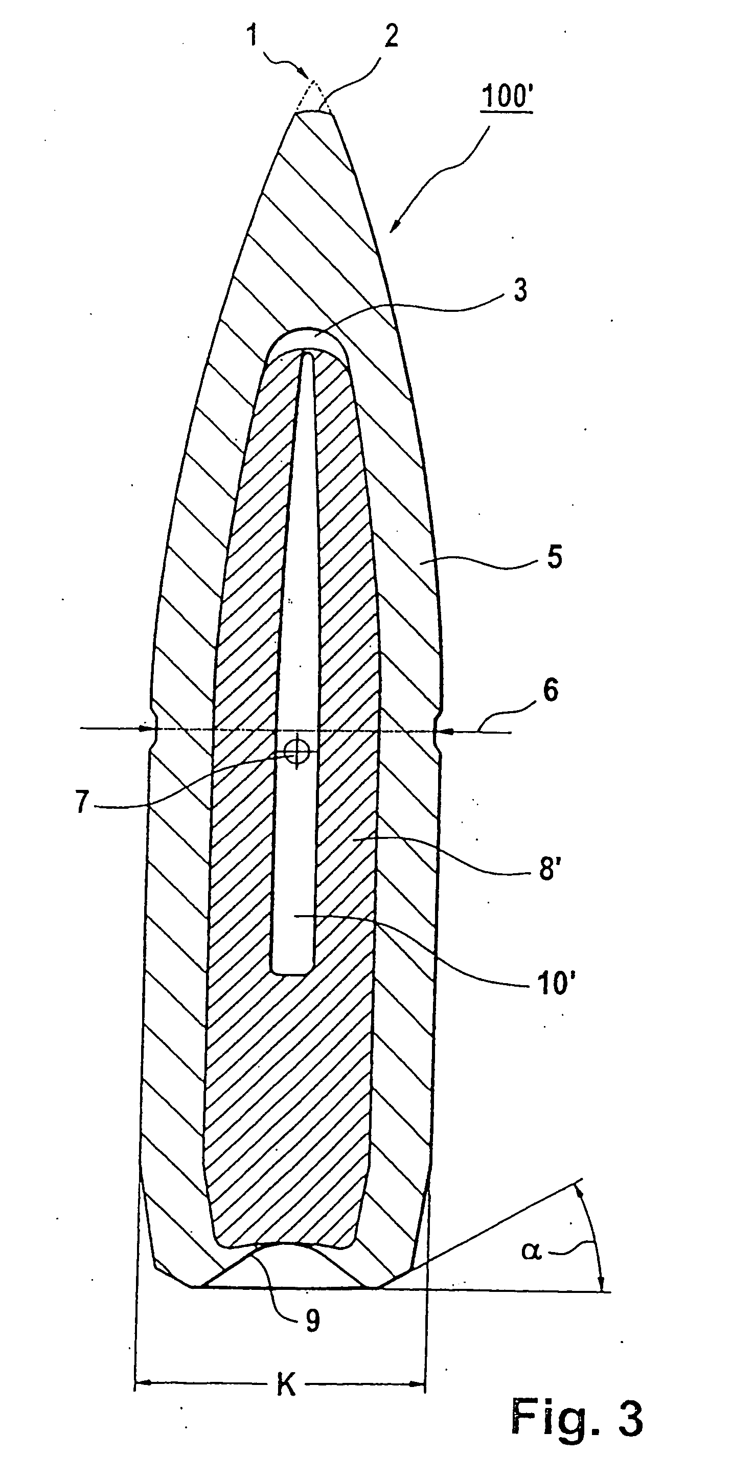
[0030] The actual tip 1 is imaginary; in reality it is a tip in the shape of a spherical cup 2 formed in the front end of outer jacket 5, the front region of which is ogical or conical. A small air space 3 is located inside the projectile 100, which is formed between a hard core 4 and the outer jacket 5, as a result of the different radii of the front portion of a central hollow space in the jacket and the front of the hard core. A jacket core 8 is ...


PUM


Abstract

A small-bore projectile comprises a ductile outer jacket, a hard core, and a hollow jacket core. Kinetic energy of the projectile is substantially transmitted to the hard core when a target is hit such that said hard core penetrates the target. The outer jacket is supported by the jacket core that is located on the inside and mushrooms up into a deformed state upon impact without fragmenting. The projectile has good flying behavior and great final ballistic performance and can be produced in an entirely lead-free manner.

Description

[0001] The present application is a Continuation of PCT International Application No. PCT / CH2005 / 000257, filed May 9, 2005. [0002] The present invention relates to a lead-free small-bore jacketed projectile. BACKGROUND OF THE INVENTION [0003] Small-bore jacketed projectile ammunition is known in various designs. It may be divided into those with hard cores made of steel, into those with hard cores made from dense sintered material and those with a medium additional to the hard core such as lead, aluminum and / or air. Together with such a core, commercially available ammunition has a steel jacket, generally configured as a full jacket, i.e. a plated steel jacket or a jacket made from a copper / zinc alloy (tombac jacket). In this connection, the jacket receives one or more cores and further media and encloses said cores and media at least in a liquid-tight manner. [0004] Small arms ammunition and a manufacturing process therefor is known from EP-A2-0 106 411. The correspondingly optimiz...

Claims


Application Information

Patent Timeline
Patent Type & Authority Applications(United States)
IPC IPC(8): F42B30/00
CPCF42B12/34F42B30/02F42B12/78F42B12/74
Inventor SPATZ, PETERBAUMGARTNER, HANSSCHAER, FRITZ
Owner RUAG AMMOTEC GMBH
Why Eureka
Try Eureka