Magnetoresistive head and a manufacturing method thereof

a technology of magnetoresistive head and manufacturing method, which is applied in the field of magnetoresistive head, can solve the problems of insufficient output, and easy steepening of height direction, and achieve the effect of maintaining electrostatic capacity to a small value and reducing the deterioration of dielectric breakdown voltag

Inactive Publication Date: 2007-09-06
WESTERN DIGITAL TECH INC
View PDF21 Cites 32 Cited by
  • Summary
  • Abstract
  • Description
  • Claims
  • Application Information

AI Technical Summary

Benefits of technology

[0008] Embodiments in accordance with the present invention reduce the influence of etching damage at junction edge of a magnetoresistive film in the sensor height direction, lower the deterioration of dielectric breakdown voltage between an upper magnetic shield layer and a lower magnetic shield layer and instability of reproducing property resulting from shield process, and maintain electrostatic capacity to a small value in a CPP magnetoresistive head. In the magnetoresistive head of the embodiment of the present invention shown in FIG. 1A, the length in the sensor height direction of bottom surface ...

Problems solved by technology

However, since it is feared that such GMR cannot provide sufficient output for the recording density higher than 9.3×109 bits per 1 cm2, investigation and development have been conducted for the tunneling magnetoresistive film and CPP-GMR film, allowing a current to flow through the stacking surfaces of sensing films, as the next generation magnetoresistive film of the GMR film.
Moreover, a problem also rises in the CPP structure head, in which when the second etching process is conducted, an edge in the sensor height direction easily becomes more steep, thereby a step is generated in the bottom surface of the upper magnetic shield layer, and such...

Method used


Image

  • Magnetoresistive head and a manufacturing method thereof
  • Magnetoresistive head and a manufacturing method thereof
  • Magnetoresistive head and a manufacturing method thereof

Examples


first embodiment

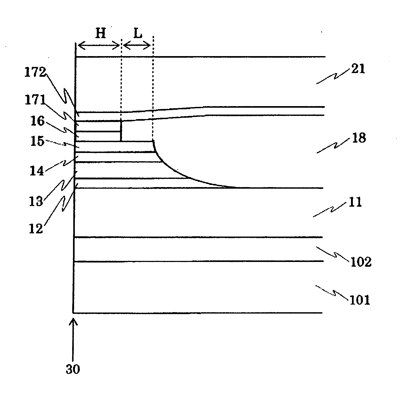
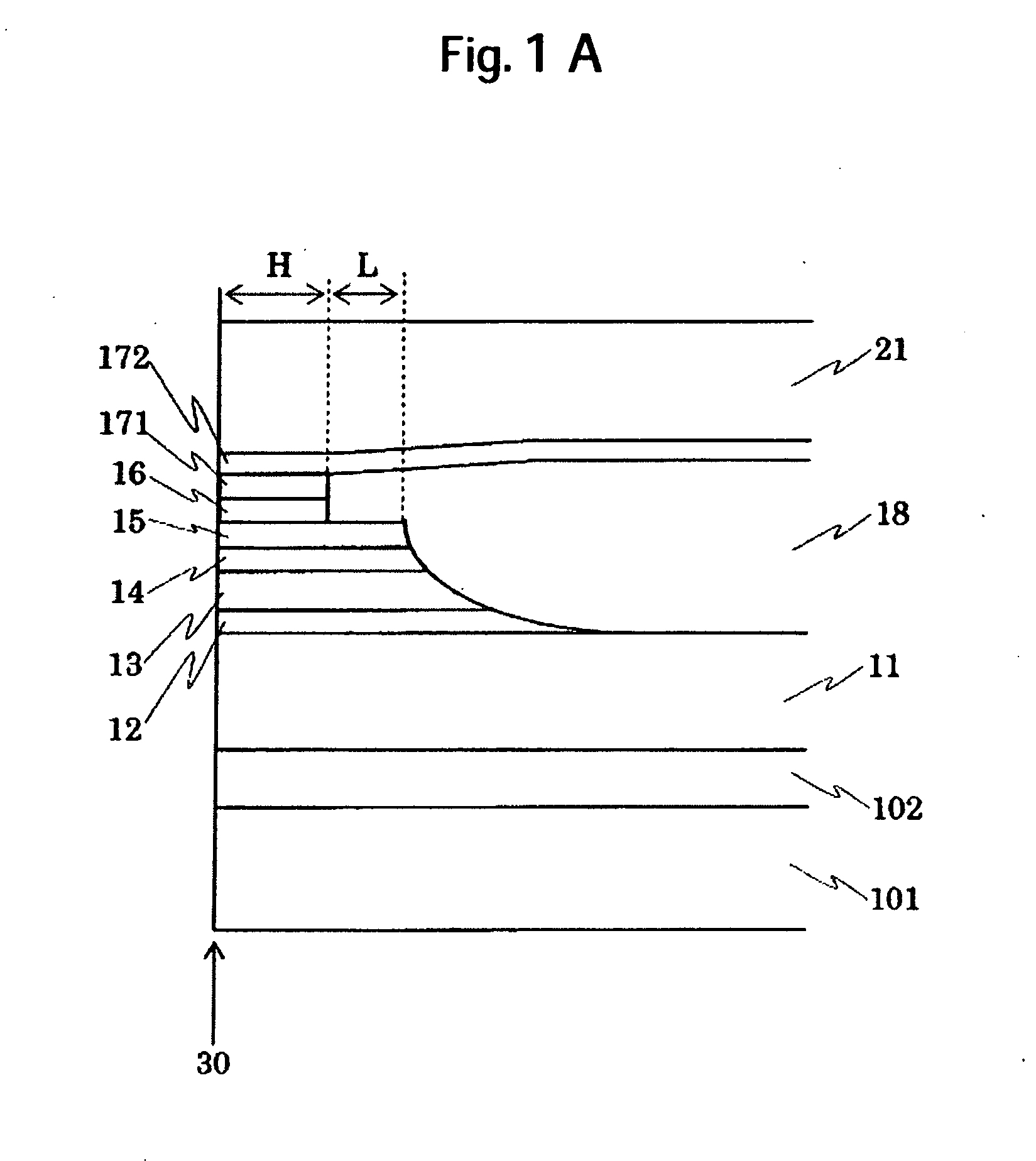
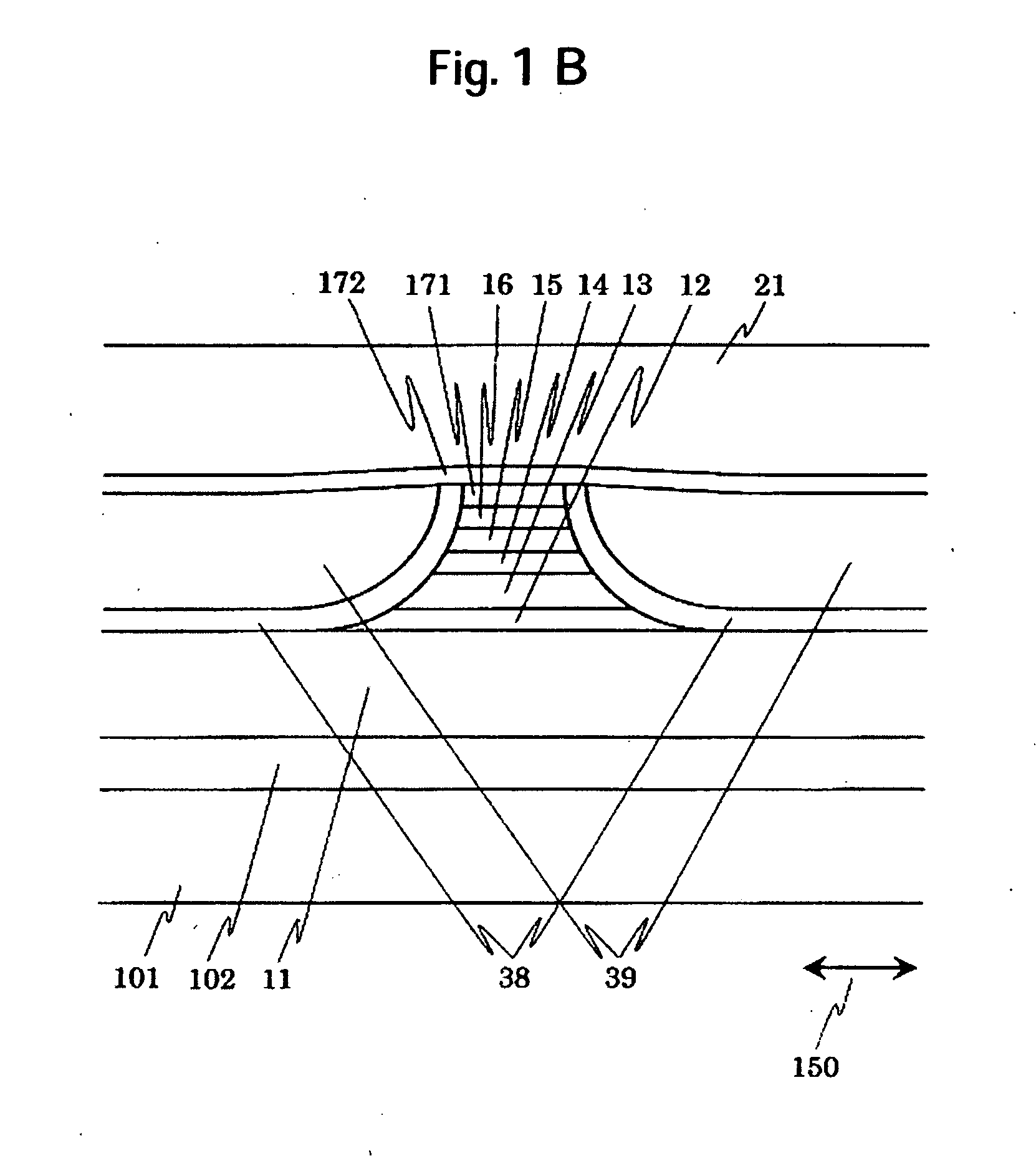
[0046]FIG. 1A shows a cross-sectional structure in the sensor height direction of a magnetic sensor of a magnetoresistive head of the present invention. For the reference, FIG. 1B shows structures in the track direction at the air bearing surface. Moreover, FIGS. 14(A)-(E) are schematic diagrams showing the processes to form the sensor height direction.

[0047] As shown in FIG. 14(A), a substrate 101 formed of a ceramic including alumina and titanium carbide is covered with an insulator film 102 such as alumina, the surface thereof is subjected to planarization with fine polishing. Thereafter, a lower magnetic shield layer 11 formed of Ni—Fe system alloy is formed. In this process, a film formed, for example, by the sputtering method, ion beam sputtering method or plating method is patterned into the predetermined shape, thereafter an insulator film of alumina is formed to the entire surface of the substrate, and the surface is subjected to the planarization with the chemical mechani...

second embodiment

[0069] In order to attain higher reproducing resolution, the distance between the lower magnetic shield layer 11 and the upper magnetic shield layer 21 must be shortened and thereby electrostatic capacity increases. A cross-sectional structure in the sensor height direction of the magnetic sensor of the magnetoresistive head of the present invention to solve the problem explained above is shown in FIG. 4.

[0070] In the first embodiment, the gradual taper at the edge in the sensor height direction of the magnetoresistive film stops at the lower gap layer 12 and the upper surface of the lower magnetic shield layer 11 is flat. Therefore, if a distance between the upper and lower magnetic shield layers is narrowed while the shape is maintained as it is, the electrostatic capacity increases. Accordingly, in this embodiment, increase in the electrostatic capacity is suppressed by widening the distance between the upper and lower magnetic shield layers at higher position along the sensor h...

third embodiment

[0071] In order to attain higher track density, side reading in the track direction must be reduced. As a means for realizing this purpose, a method has been proposed, in which the side shield is allocated in both sides of the magnetic sensor in the track direction. In this case, it is desirable to introduce the so-called in-stack biasing structure wherein a longitudinal biasing layer is stacked in the upper or lower side of the magnetoresistive film.

[0072]FIG. 5 shows a cross-sectional structure in the sensor height direction of the magnetic sensor of the magnetoresistive head of an embodiment of the present invention which is suitable for the in-stack biasing structure. In the basic in-stack biasing structure, a first pinning layer for pinning magnetization of the first ferromagnetic layer and a second pinning layer for pinning, in the track direction, magnetization of the longitudinal biasing layer 24 provided to applying the longitudinal biasing field to the second ferromagneti...


PUM


Abstract

Embodiments in accordance with the present invention reduce the influence of etching damage at junction edge of a magnetoresistive film in the sensor height direction, lower the deterioration of dielectric breakdown voltage between an upper magnetic shield layer and a lower magnetic shield layer and instability of reproducing property resulting from shield process, and maintain electrostatic capacity to a small value in a CPP magnetoresistive head. In an embodiment of a magnetoresistive head of the present invention, length in the sensor height direction of bottom surface of a pinning layer is longer than the length in the sensor height direction of bottom surface of a first ferromagnetic layer. The angle formed by an edge in the sensor height direction of the pinning layer to the surface extended from a bottom surface of a magnetoresistive film is smaller than the angle formed by an edge in the sensor height direction of a second ferromagnetic layer to the surface extended from a bottom surface of the magnetoresistive film. Height of top surface of a sensor height direction refill film is equal to or higher than the top surface of the magnetoresistive film.

Description

CROSS-REFERENCES TO RELATED APPLICATIONS [0001] The instant nonprovisional patent application claims priority to Japanese Patent Application 2006-036092, filed Feb. 14, 2006 and incorporated by reference herein for all purposes. BACKGROUND OF THE INVENTION [0002] A magnetoresistive sensor utilizing magnetoresistive effect in which an electric resistance changes in accordance with change in an external magnetic field has been known as an excellent magnetic field sensor and has been put into the practical use as a read head of magnetic head which is the principal component of a magnetic storage apparatus. Since the magnetic storage apparatus is continuously progressing in reduction in size and higher speed transfer, higher performance is also required for a magnetic head for reading and writing information. Measures for realization of higher output and higher transfer rate may be listed as the principal subjects of the read head among such requirement. In regard to higher output, deve...

Claims


Application Information

Patent Timeline
IPC IPC(8): G11B5/33
CPCG11B5/3163G11B5/398G11B5/3903
Inventor WATANABE, KATSUROSHINTANI, TAKUUEDA, KAZUHIROOSUGI, MASAHIRO
Owner WESTERN DIGITAL TECH INC
Why Eureka
Try Eureka