
Optical information detecting method, optical information detector, data sampling method

a technology of optical information and detection method, applied in the direction of digital signal error detection/correction, instruments, television systems, etc., can solve the problems of inability to obtain accurate information, image of the data page detected by the light receiving device can be severely degraded, and the storage density is too low, so as to efficiently detect optical information stored

Inactive Publication Date: 2007-09-06
TAIWAN SEMICON MFG CO LTD
View PDF13 Cites 6 Cited by
  • Summary
  • Abstract
  • Description
  • Claims
  • Application Information

AI Technical Summary

Benefits of technology

[0022]The present invention is contrived to solve the above-mentioned problems. An object of the invention is to provide an optical information detecting method which can efficiently detect optical information stored in an optical information recording medium by using a 1:N over-sampling method (where N is greater than 1) and a balanced code.
[0023]Another object of the invention is to provide an optical information detector which can efficiently detect optical information stored in an optical information recording medium by using a 1:N over-sampling method (where N is greater than 1).
[0024]Another object of the invention is to provide a data sampling method which can efficiently sample optical information at the time of performing a 1:N over-sampling method (where N is greater than 1).

Problems solved by technology

The signal beam and the reference beam interfere with each other in the optical information recording medium and the images of the data pages loaded to the signal beams are recorded in the form of interference patterns in the optical information recording medium.
At the time of actually reproducing the image of the data page, the position of the reproduced image formed on the light receiving device varies due to shrinkage or rotation of the optical information recording medium, and misalignment is caused.
However, in the 1:1 pixel matching method, when two kinds of pixels depart from each other by a half or more size of the data pixel, the image of the data page detected by the light receiving device can be severely degraded.
When the departure of pixels is severe, it is not possible to obtain accurate information.
However, in the 1:3 over-sampling method, since 9 detection pixels are required for detecting one data pixel at the time of detecting the image, the storage density is too low.
However, in comparison with the pixel matching method, the 1:2 over-sampling method has a disadvantage that the storage density is 25% of that of the pixel matching method.
The known pixel matching method has an advantage of a large storage density but has a disadvantage of misalignment between pixels.
The known 1:3 over-sampling method and 1:2 over-sampling method have an advantage of high reliability in detecting data but have a disadvantage of too small storage density.

Method used


Image

  • Optical information detecting method, optical information detector, data sampling method
  • Optical information detecting method, optical information detector, data sampling method
  • Optical information detecting method, optical information detector, data sampling method

Examples


Embodiment Construction

[0041]Hereinafter, exemplary embodiments of the present invention will be described in detail with reference to the attached drawings.

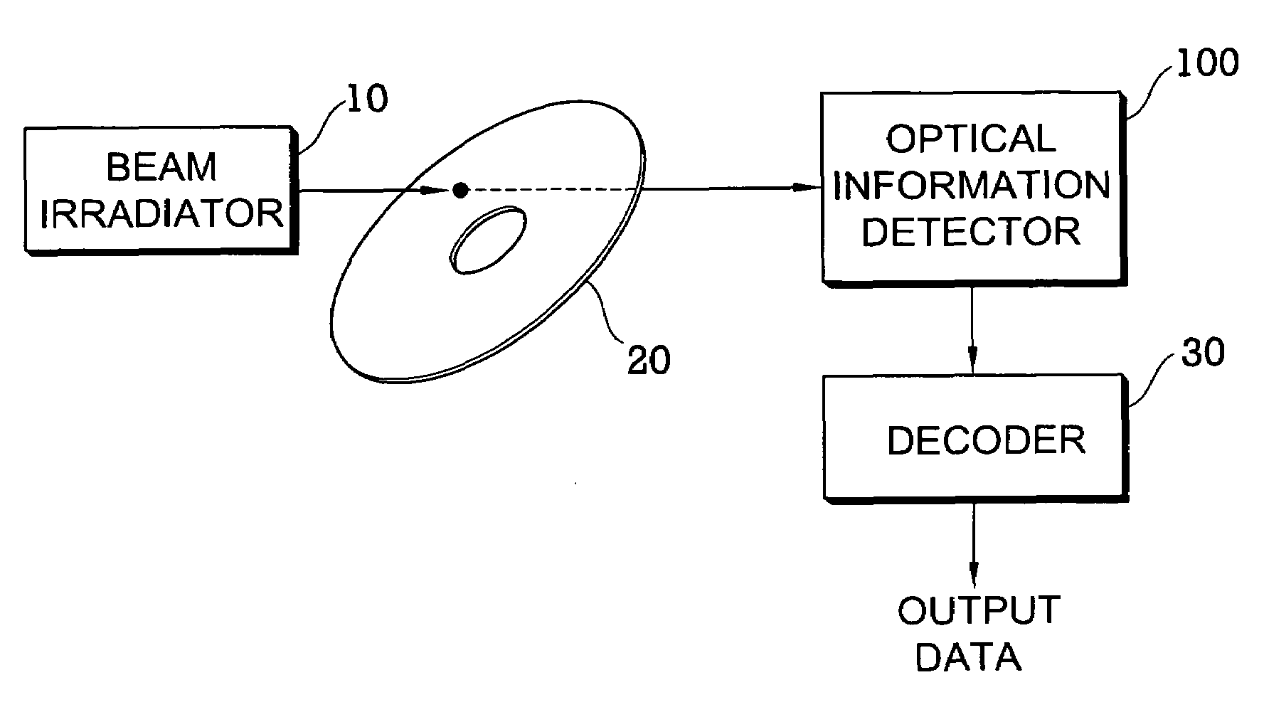
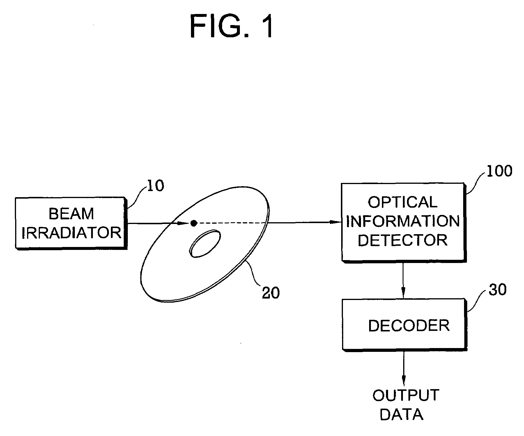
[0042]FIG. 1 is a block diagram illustrating a configuration of an optical information reproducing apparatus having an optical information detector according to an exemplary embodiment of the invention.

[0043]Referring to FIG. 1, the optical information reproducing apparatus includes a beam irradiator 10 generating a beam such as a laser beam and irradiating the beam to an optical information recording medium 20. The beam irradiated from the beam irradiator 10 is incident on the optical information recording medium 20 at a predetermined angle. A plurality of data pages is stored in the form of interference patterns in the optical information recording medium 20. The interference pattern may be a holographic interference pattern. The beam irradiated from the beam irradiator 10 may be one of a reference beam for reproducing the holographic interference p...


PUM

PropertyMeasurementUnit
light intensity distributionaaaaaaaaaa
optical distributionaaaaaaaaaa
areaaaaaaaaaaa

Abstract

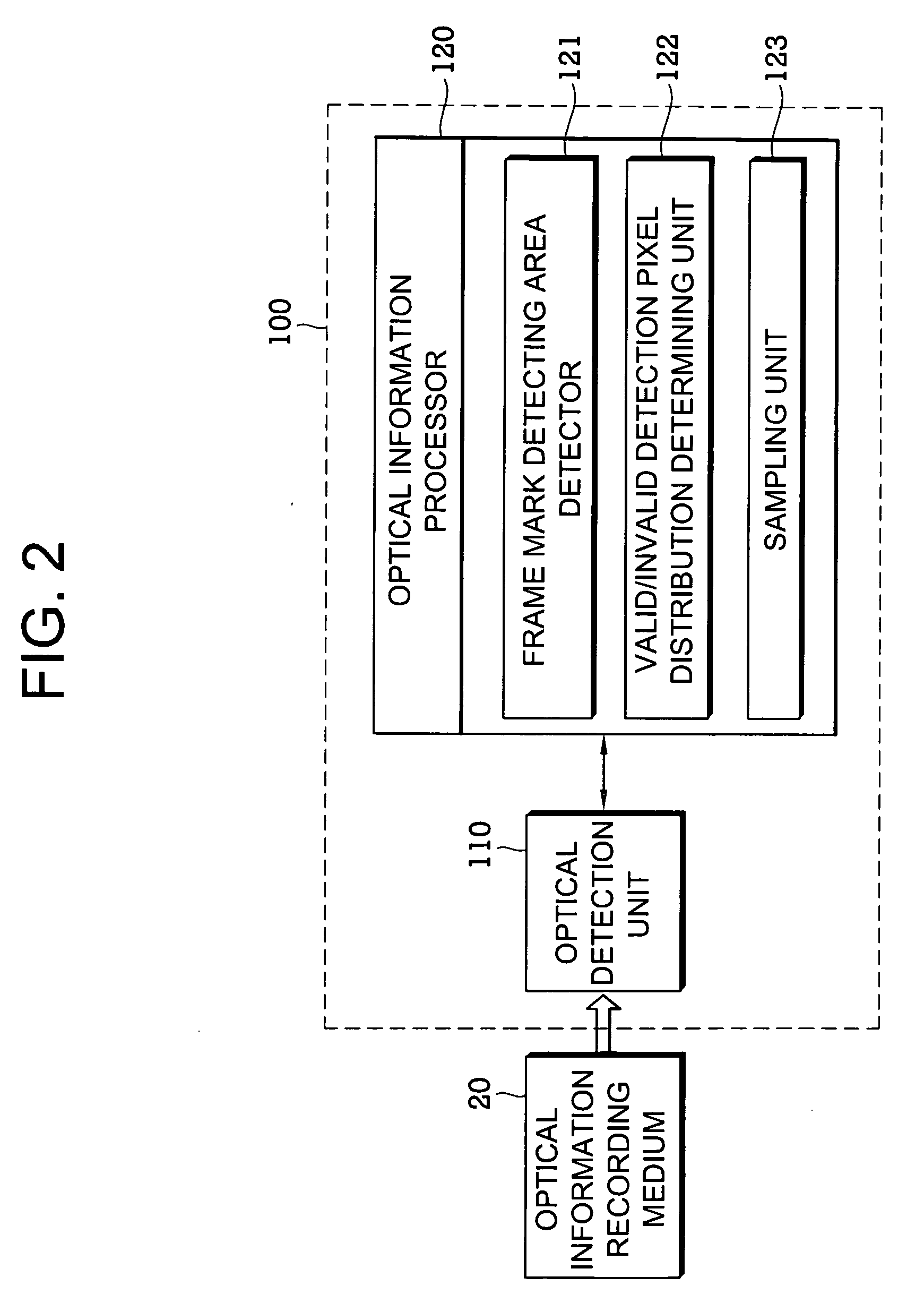
There is provided an optical information detecting method. The method includes: detecting an image of a source data page coded with balanced codewords by the use of 1:N (where N is greater than 1) excessive detection pixels; determining a distribution pattern of valid detection pixels and invalid detection pixels to be corrected in the detected image by the use of a light intensity distribution of the detected image; and dividing the detected image into balanced codeword detecting areas corresponding to the balanced codewords and sampling data of the balanced codeword detecting areas by the use of the determined distribution pattern and an optical distribution characteristic of the balanced codewords. Accordingly, it is possible to efficiently detect optical information by the use of a 1:N over-sampling method. Specifically, the distribution pattern of valid detection pixels and invalid detection pixels in the detected image of a data page can be properly used to sample a balanced code.

Description

BACKGROUND[0001]1. Technical Field[0002]The present invention relates to an optical information detecting method, an optical information detector, and a data sampling method, and more particularly, to an optical information detecting method, an optical information detector, a data sampling method, in which optical information can be efficiently detected from an optical information recording medium.[0003]2. Related Art[0004]Recently, with increase in requirement for a next-generation storage system having large storage capacity, an optical information processing system using holography, that is, a holographic optical information processing system, has attracted attention.[0005]In the holographic optical information processing system, by irradiating a signal beam containing data and a reference beam at an angle different from that of the signal beam to a predetermined position of an optical information recording medium and intersecting two beams each other, an interference pattern is ...

Claims


Application Information

Patent Timeline
Patent Type & Authority Applications(United States)
IPC IPC(8): G11B7/24
CPCG11B7/0065G11B20/18H04N5/90H03M5/145G11B2220/2504G11B20/10
Inventor YOON, PIL-SANGKIM, HAK-SUNHWANG, EUI-SEOK
Owner TAIWAN SEMICON MFG CO LTD
Learn More