
Ink jet recording head and manufacturing method of the same

a technology of recording head and ink jet, which is applied in the field of recording head, can solve the problems of excessive irradiation of flow path pattern, reduce the thickness of orifice plate, and reduce the diameter of each ink discharge port, and achieve the effect of high-quality printing

Inactive Publication Date: 2007-09-06
CANON KK
View PDF13 Cites 24 Cited by
  • Summary
  • Abstract
  • Description
  • Claims
  • Application Information

AI Technical Summary

Benefits of technology

The present invention provides an ink jet recording head and a manufacturing method that can perform high-quality printing while ensuring sufficient adhesion between the coating resin layer and the substrate, regardless of the thickness of the orifice plate and the coating resin layer. The manufacturing method includes exposing and developing the coating resin layer to form ink discharge ports, and dissolving and removing the mold material to form a liquid flow path. The method also includes exposing the coating resin layer in two stages, with more exposure energy applied to the region of the coating resin layer positioned above the mold material. The invention can prevent cracks and printing defects, resulting in a stable ink discharge and high-quality printing.

Problems solved by technology

The technique has a tendency to reduce a thickness (a thickness of an orifice plate) of the coating resin layer to be formed on the mold material and a tendency to reduce a diameter of each ink discharge port.
However, if the thickness of the orifice plate decreases, the coating resin layer above the ink flow path pattern might be excessively irradiated with the heretofore applied exposure energy, and sag and shape change of pattern edges might be generated.
Therefore, it is difficult to highly precisely form micro ink discharge ports and polygonal ink discharge ports.
Since light is transmitted through the coating resin layer, there is fear of an influence of reflection of the light from the substrate.
Furthermore, owing to the excessive irradiation, a part of the resin constituting the mold material is sometimes sensitized and depolymerized with the exposure energy transmitted through the coating resin layer.
This depolymerized resin is easily damaged by a development liquid during the next developing step, and cracks might be generated.
The generated cracks grow into voids in the mold material and an interface between the mold material and the coating resin layer owing to thermal history during the subsequent steps, finally destroy a protective material during anisotropic etching of the substrate and deteriorate a protecting function.
This causes unstable ink discharge and deteriorates a printing quality owing to disturbance of an ink discharge direction.
Therefore, a problem similar to the above problem easily occurs.
If the exposure energy is reduced in order to inhibit the above sag and shape change of the pattern edges and inhibit the generation of the cracks in the mold material, it is difficult to secure sufficient adhesion between the coating resin layer and the substrate.
That is, it has been difficult to manufacture an ink jet recording head capable of performing high-quality printing while securing the sufficient adhesion between the coating resin layer and the substrate, depending on the thicknesses of the orifice plate and the coating resin layer.

Method used


Image

  • Ink jet recording head and manufacturing method of the same
  • Ink jet recording head and manufacturing method of the same
  • Ink jet recording head and manufacturing method of the same

Examples


examples 1 and 2

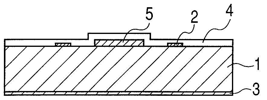
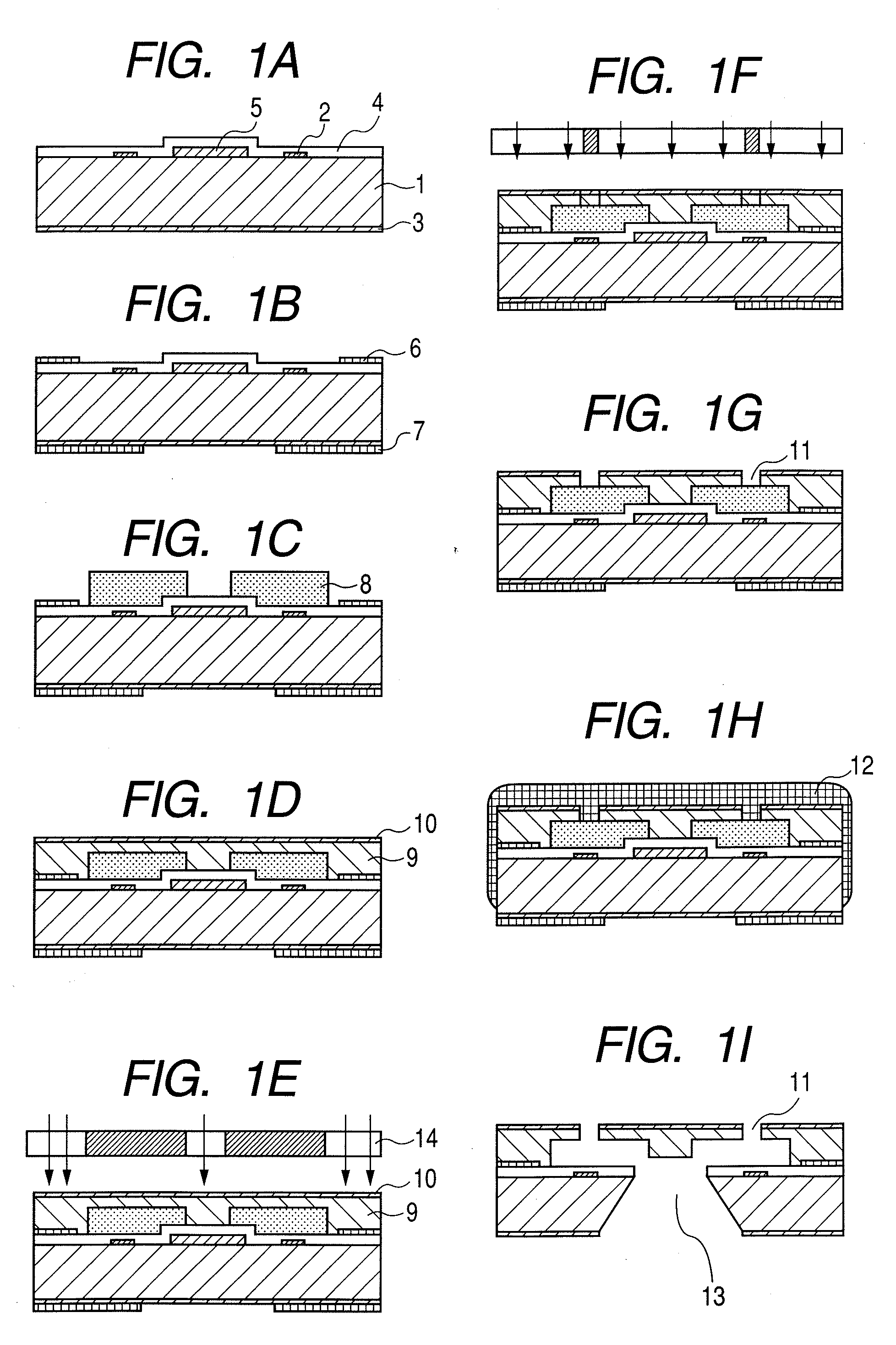
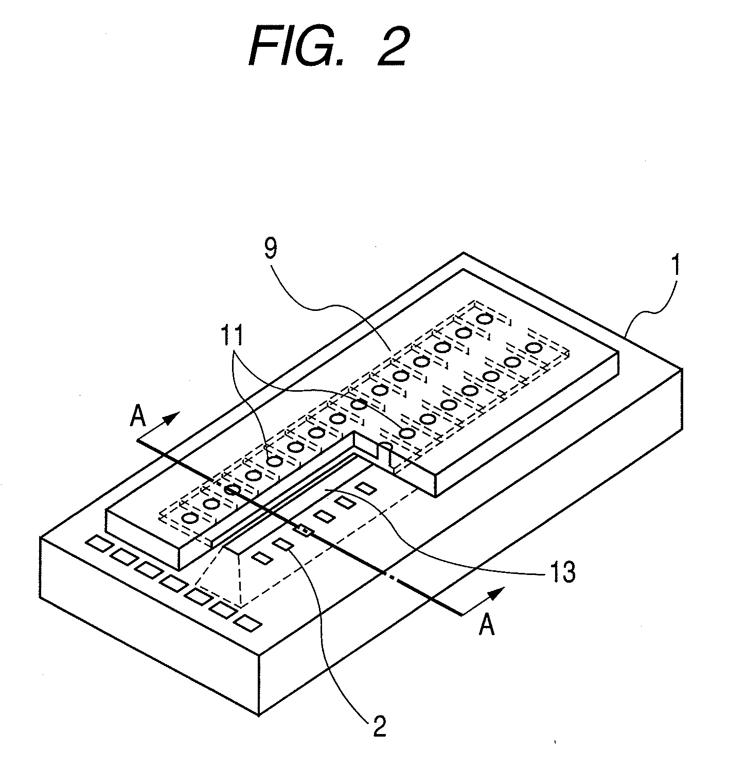
[0026]FIGS. 1A to 1I are schematic sectional views illustrating one embodiment of a manufacturing method of an ink jet recording head according to the present invention. It is to be noted that FIGS. 1A to 1I correspond to schematic sectional views cut along the A-A line of FIG. 2 which is a partially cut perspective view schematically illustrating a part of the ink jet recording head.

[0027]First, as shown in FIG. 1A, an energy generating element 2 such as a heating resistive element is arranged on the surface of a substrate 1. As the substrate 1, for example, a silicon substrate of a crystal orientation can be used. As shown in FIG. 1A, a protective layer 4 and a sacrifice layer 5 are formed on the surface of the substrate 1 as desired, and a SiO2 film 3 is formed on the backside of the substrate 1 as desired.

[0028]Furthermore, as shown in FIG. 1B, an adhesion enhancing layer 6 can be formed on the surface of the substrate 1, and a polyether amide resin layer 7 can be formed on the...


PUM

PropertyMeasurementUnit
thicknessaaaaaaaaaa
thicknessaaaaaaaaaa
thicknessesaaaaaaaaaa

Abstract

A manufacturing method of an ink jet recording head has: forming a liquid flow path mold material of a soluble resin on a substrate on which an energy generating elements is formed, the energy generating element being configured to generate energy for use in discharging ink; forming a coating resin layer of a negative photosensitive resin on the substrate on which the mold material is formed; exposing and developing the coating resin layer to form an ink discharge port in the coating resin layer; and dissolving and removing the mold material to form a liquid flow path, wherein during the exposing of the coating resin layer, a total amount of exposure energy per unit area, applied to an exposure region other than a region of the coating resin layer positioned above the mold material, is larger than that of exposure energy per unit area, applied to the region of the coating resin layer positioned above the mold material.

Description

BACKGROUND OF THE INVENTION[0001]1. Field of the Invention[0002]The present invention relates to an ink jet recording head for use in an ink jet recording system and a manufacturing method of the head.[0003]2. Description of the Related Art[0004]An ink jet recording head applied to an ink jet recording system includes a generally fine ink discharge port, a liquid flow path and an ink discharge energy generating element arranged in a part of the liquid flow path.[0005]Heretofore, as a method of manufacturing such an ink jet recording head, U.S. Pat. No. 5,478,606 discusses a method having the following steps: (1) a step of forming a pattern which constitutes an ink flow path mold material of a soluble resin on a substrate on which ink discharge pressure generating elements are formed; (2) a step of dissolving a coating resin including a photosensitive resin, and coating a layer of the soluble resin with the solvent to thereby form a coating resin layer which constitutes an ink flow p...

Claims


Application Information

Patent Timeline
Patent Type & Authority Applications(United States)
IPC IPC(8): G03C5/00
CPCB41J2/1604B41J2/1628B41J2/1629B41J2/1631B41J2002/14475B41J2/1635B41J2/1639B41J2/1645B41J2/1632
Inventor MURAYAMA, HIROYUKIKOBAYASHI, JUNICHITAGAWA, YOSHINORIFUJII, KENJITAMURA, HIDEOYONEMOTO, TAICHIWATANABE, KEIJI
Owner CANON KK
Learn More