System for functional electrical stimulation

a functional electrical stimulation and functional technology, applied in the field of functional electrical stimulation systems, can solve the problems of insufficient physical strain in the daily life of typical sci individuals to improve or maintain physical capacity, increase the risk of secondary diseases, and all three approaches suffer from significant limitations that confine their widespread us

Inactive Publication Date: 2007-09-06
ALFRED E MANN FOUND FOR SCI RES
View PDF32 Cites 99 Cited by
  • Summary
  • Abstract
  • Description
  • Claims
  • Application Information

AI Technical Summary

Problems solved by technology

Researchers in this area of research have proposed that the physical strain in the daily life of typical SCI individuals is insufficient to improve or maintain physical capacity.
As a result, SCI individuals are at the lower end of the aerobic fitness spectrum which puts them at an increased risk for secondary diseases, such as obesity, insulin resistance, hyperglycemia, diabetes, and cardiovascular disease.
All three approaches suffer from significant limitations that confine their widespread use.
The transcutaneous approach requires extensive time commitment and personal assistance to don and doff the electrodes, the repeatability of electrode placement is poor, and the pain elicited by transcutaneous stimulation in individuals with incomplete injury is a hindrance.
The percutaneous approach also requires time commitment in maintaining the site where the electrodes exit this skin.
This site is prone to infection and is generally unacceptable to many subjects on principle.
Although the fully implantable approach presented great promise, it failed to deliver due to its high level of invasiveness, risk of infection spreading throughout the system, and its lack of flexibility in application.

Method used


Image

  • System for functional electrical stimulation
  • System for functional electrical stimulation
  • System for functional electrical stimulation

Examples


Embodiment Construction

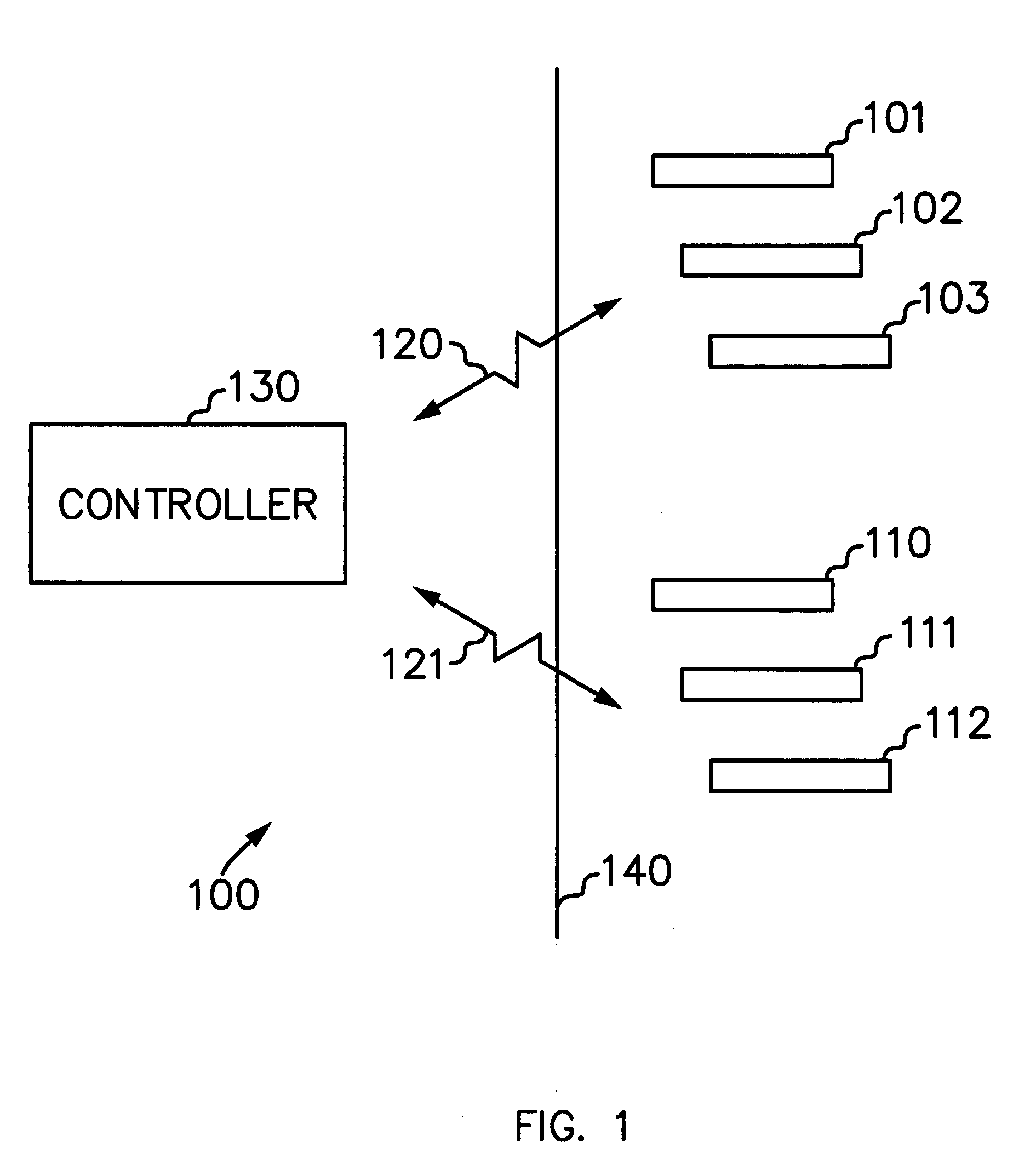
[0022]FIG. 1 is a simplified block diagram of a system 100 for functional electrical stimulation (FES). Stimulators 101, 102 and 103 and sensors 110, 111 and 112 are implanted below the skin 140 of a person. Controller 130 is a system control unit and communicates with the stimulators 101, etc. via wireless communications link 120. Controller 130 also communicates with sensors 110, etc. via wireless communications link 121. Stimulators 101, etc. and sensors 110, etc. can be battery powered and receive power from controller 130 through a coil (not shown) generating a magnetic field. Controller 130 includes a closed loop control system, which uses feedback received from a variety of sensors to control the FES during an exercise session. Implanted stimulators, implanted sensors and the wireless control of stimulators and sensors are described in U.S. Pat. Nos. 5,193,539; 5,193,540; 5,324,316; 5,405,367; 6,175,764; 6,181,965; 6,185,452; 6,185,455; 6,208,894; 6,214,032; and 6,315,721, wh...


PUM


Abstract

An exercising system and method for the treatment and rehabilitation of the paralyzed muscles of the legs. Stimulators and sensors are implanted in several of the main muscle groups of the legs. A computerized controller uses wireless signals for communications with the implanted stimulators and sensors. The person receiving the treatment sits on an exercise machine such as a stationery bicycle, a leg press, a rowing machine or other leg exercising machine. The controller determines the position of the legs and transmits a series of commands to the stimulators to provide functional electrical stimulation (FES) to the muscles of the legs, which move the legs in a cyclical or reciprocating manner, such as that needed to pedal a bicycle. Using data provided by the implanted sensors, the controller is able to adjust the stimulation commands sent to the muscles of the legs to control the amount of force exerted by the foot, to limit user fatigue and to keep the foot in a neutral position on the pedal or footrest. Users of the system who are partially paralyzed in the legs can receive an implanted EMG sensor and the controller can synchronize the stimulation of their paralyzed leg muscles with the user's own voluntary activation of their leg muscles.

Description

CROSS REFERENCE TO RELATED APPLICATIONS [0001] This application claims the benefit of U.S. Provisional Application No. 60 / 774,405 filed on Feb. 17, 2006 entitled: “Closed Loop Control System for Constant Speed Functional Electrical Stimulation Cycling”BACKGROUND OF THE INVENTION [0002] There are a substantial number of people who have either partial or full paralysis of the legs due to spinal cord injury (SCI). In the United States, it is estimated that there are approximately 200,000 people with SCI. Each year, there are more than 10,000 new cases of SCI. SCI and its associated lower limb paralysis leads to neuromusculoskeletal disorders such as osteoporosis, disuse atrophy, spasticity, muscle and joint contractures, cardiopulmonary dysfunction, and loss of muscle endurance and metabolic function. Researchers in this area of research have proposed that the physical strain in the daily life of typical SCI individuals is insufficient to improve or maintain physical capacity. As a res...

Claims


Application Information

Patent Timeline
Patent Type & Authority Applications(United States)
IPC IPC(8): A61N1/18
CPCA61N1/36003A61N1/3787A61N1/37288
Inventor KUSCHNER, DOUGHAN, DANHANSEN, MORTENMOBLEY, JON PHILSCHULMAN, JOSEPH H.
Owner ALFRED E MANN FOUND FOR SCI RES
Why Eureka
Try Eureka