Water-cooling heat dissipation device and water block for the same

a technology of water cooling and heat dissipation device, which is applied in the direction of laminated elements, lighting and heating apparatus, and semiconductor/solid-state device details, etc. it can solve the problems of user annoyance, noise caused by high-speed fans, and difficulty in improving, so as to enhance the performance of the water block and ensure heat exchange

Inactive Publication Date: 2007-09-13
COOLER MASTER CO LTD
View PDF4 Cites 13 Cited by
  • Summary
  • Abstract
  • Description
  • Claims
  • Application Information

AI Technical Summary

Benefits of technology

[0007]The present invention is to provide a water block formed by continuously bending metal plates, whereby dense heat-dissipating plates and larger heat-dissipating area can be provided within a limited space. The heat-dissipating plates have sufficient heat exchange with the cooling liquid to enhance the performance of the water block.

Problems solved by technology

The air-cooling type heat dissipation device is sufficient for conventional computer because the central processing unit (CPU) of those computers is not fast.
However, the heat dissipation device is generally constrained by the space in the chassis of computer and is difficult to improve with the pace of CPU.
Moreover, the noise caused by high-speed fan is also a problem, which annoys user.
Therefore, it is important issue to provide a water-cooling type and associated water block with high efficiency and low noise.
However, the prior art water block has following drawbacks.
The molding dies have considerable cost and different molding dies are necessary for different electronic devices.
Therefore, the cost for the prior art water block is difficult to reduce.
Moreover, for press-molding or extruding process, the height and thickness of heat-dissipating plates and separation between the heat-dissipating plates are limited by molding die, material viscosity and mold-releasing tolerance.
Moreover, the heat-dissipating plate has smooth surface and cooling liquid fast flows through the heat-dissipating plate such that the cooling liquid has poor heat exchange property with the water-cooling devices.

Method used


Image

  • Water-cooling heat dissipation device and water block for the same
  • Water-cooling heat dissipation device and water block for the same
  • Water-cooling heat dissipation device and water block for the same

Examples


Embodiment Construction

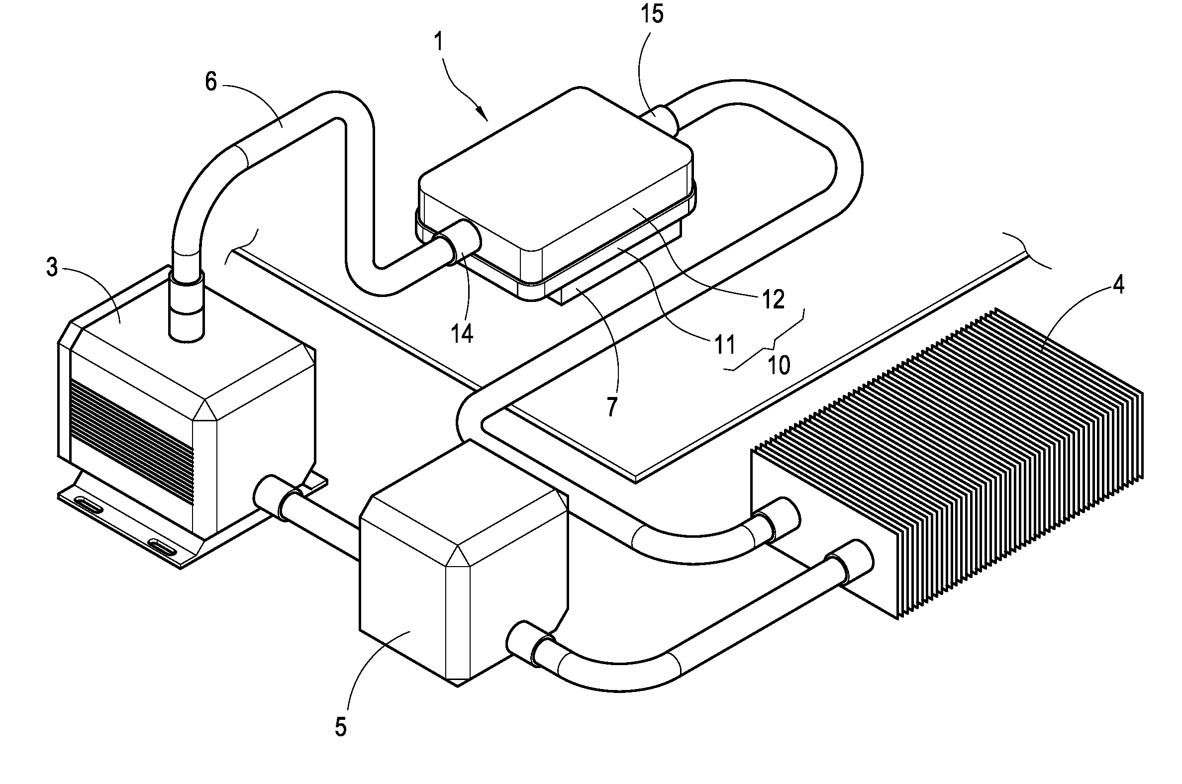
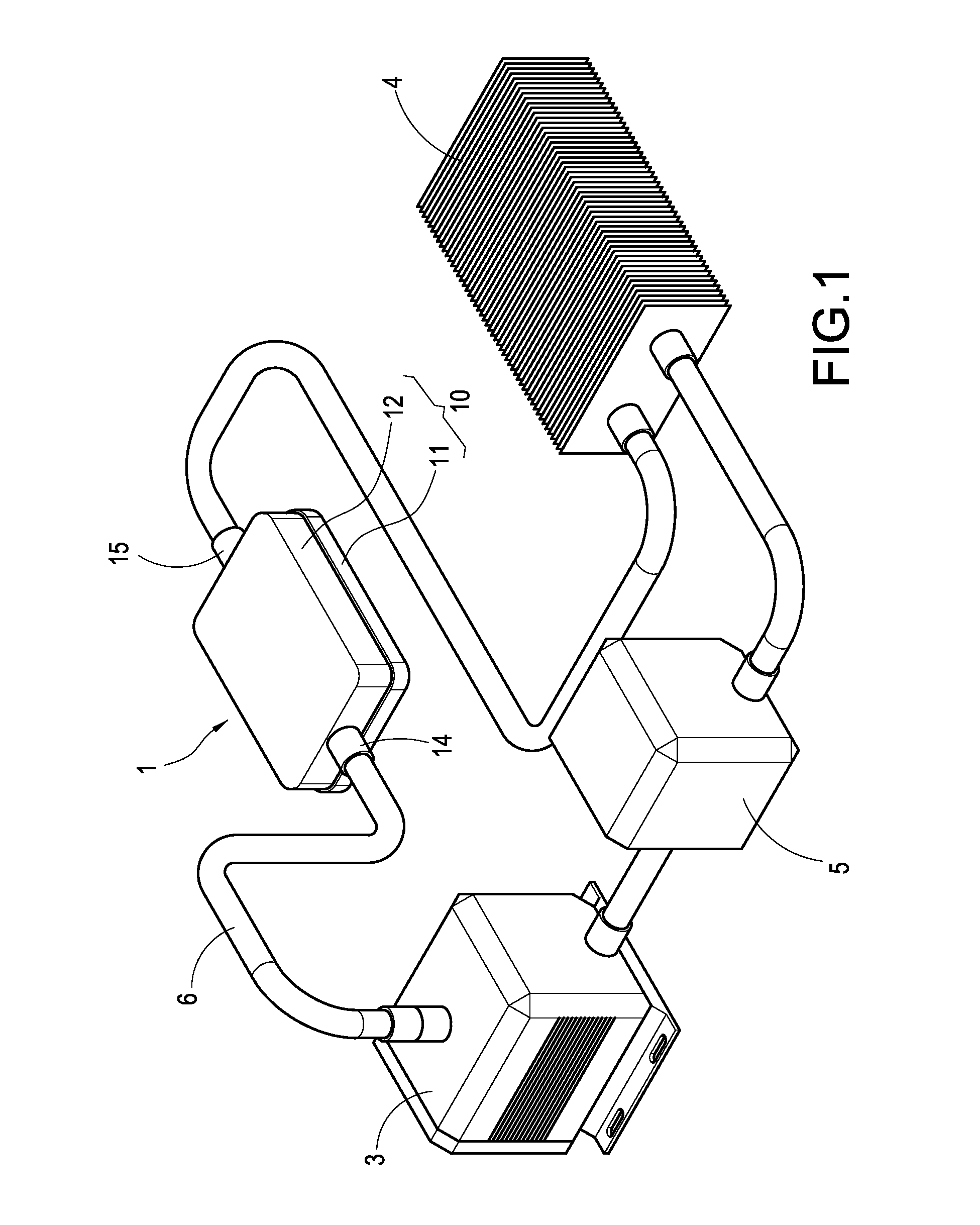
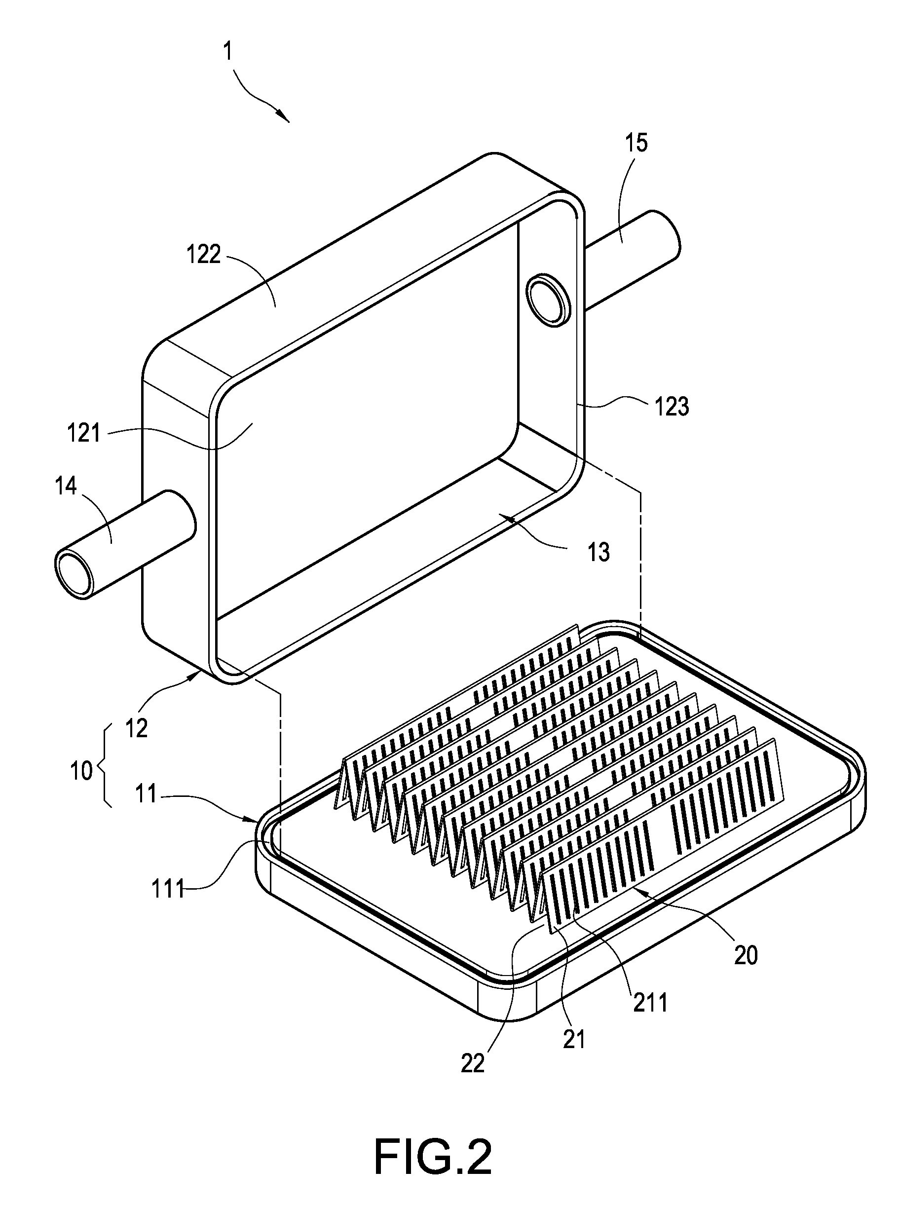
[0022]With reference to FIGS. 1 to 3, the present invention provides a water-cooling heat dissipation device and the water block thereof. The water-cooling device mainly comprises a water block 1, a pump 3, a radiator 4, a water tank 5 and a plurality of water hoses 6, where the water block 1 comprises a casing 10 and a metal panel 20.

[0023]The casing 10 comprises a heat-conducting base 11 and a cover 12 covering the top of the heat-conducting base 11. A hollow and closed cavity 13 is defined between the heat-conducting base 11 and the cover 12. The heat-conducting base 11 is made of material with good thermal conduction and comprises an annulus groove 111 at topside thereof. The heat-conducting base 11 comprises a round bump 112 downward extended from bottom thereof. The cover 12 comprises a closing plate 121 and a side plate 122 vertically extended from the closing plate 121. An opening 123 is defined at end of the side plate 122 and covers topside of the heat-conducting base 11. ...


PUM

PropertyMeasurementUnit
heat-conductingaaaaaaaaaa
heat-aaaaaaaaaa
heat-dissipatingaaaaaaaaaa

Abstract

A water-cooling heat dissipation device includes a water block and a pump communicated with the water block and having cooling liquid therein. The water-cooling includes a casing and a metal panel, where the casing includes a hollow and closed cavity, a water inlet and a water outlet outside the casing and communicated with the cavity. The metal panel includes a plurality of continuously-bent heat-dissipating plates, a heat-dissipating channel defined between two adjacent heat-dissipating plates, one end of the heat-dissipating plate is attached to bottom of the cavity of the casing. Therefore, the heat-dissipating plate has more contact area with the cooling liquid in a limited space to increase heat exchange effect.

Description

BACKGROUND OF THE INVENTION[0001]1. Field of the Invention[0002]The present invention relates to a water-cooling heat dissipation device and water block for the same, especially to a water-cooling heat dissipation device for electronic device and water block for the same.[0003]2. Description of Prior Art[0004]The air-cooling type heat dissipation device is sufficient for conventional computer because the central processing unit (CPU) of those computers is not fast. As the operation clock of present CPU exceeds 3 GHz, heat is increased with proportion to the operation clock. However, the heat dissipation device is generally constrained by the space in the chassis of computer and is difficult to improve with the pace of CPU. Moreover, the noise caused by high-speed fan is also a problem, which annoys user. Therefore, it is important issue to provide a water-cooling type and associated water block with high efficiency and low noise.[0005]The conventional water block, such as that discl...

Claims


Application Information

Patent Timeline
Patent Type & Authority Applications(United States)
IPC IPC(8): B29C47/88F24H3/02
CPCF28D15/00F28F3/027F28F3/12H01L23/473H01L2924/0002H01L2924/00
Inventor PENG, YU-HUANG
Owner COOLER MASTER CO LTD
Why Eureka
Try Eureka