Kneading extruder

a technology of extruder and kneading, which is applied in the direction of mixing/kneading with horizontally mounted tools, clay mixing apparatus, rotary stirring mixers, etc. it can solve the problems of condensing or clumping of filler, reducing the dispersion state of filler, and reducing the inner wall f and/or the tip portion g of the cylinder, so as to reduce the inner pressure generated at the plasticization

Active Publication Date: 2007-09-13
JAPAN STEEL WORKS LTD
View PDF37 Cites 15 Cited by
  • Summary
  • Abstract
  • Description
  • Claims
  • Application Information

AI Technical Summary

Benefits of technology

[0041]As described above, according to the invention, the twist kneading disks having the foregoing predetermined requirements are incorporated in the plasticization kneading portion in the position at the length of more than 1.9 times the cylinder inner diameter. Therefore, the inner pressure generated at the plasticization kneading portion is reduced, and the abrasion of the cylinder and screws can be reduced.
[0042]Further, according to the invention, the twist kneading disks having the foregoing predetermined requirements are incorporated in the plasticization kneading portion in the position at the length of more than 1.9 times the cylinder inner diameter. Therefore, the inner pressure generated at the plasticization kneading portion is reduced, and an energy given to the solid plastic material is reduced, thus, it is possible to perform the extrusion in low temperature.
[0043]Still further, according to the invention, the twist kneading disks having the foregoing predetermined requirements are incorporated in the molten kneading dispersion portion in the position at the length of more than 1.9 times the cylinder inner diameter. Therefore, the inner pressure generated at the molten kneading dispersion portion is reduced, and the dispersion of filler can be enhanced without producing a condensed product from the filler.

Problems solved by technology

Particularly, there has been a problem that the cylinder inner wall F and / or the tip portion G is abraded away because the tip portion G of one kneading wing paired with the other tip portion G where a pressure is generated at both the tip portions of kneading wing, is contacted with the cylinder inner wall F.
In the molten kneading dispersion portion 12, there has also been a problem that the filler is condensed or clumped together, and the dispersion state of the filler becomes worse because of the force (inner pressure) generated at the tip portion G by the cylinder inner wall F and the tip of the kneading wing.
Thus, the plastic material cannot be blocked by a single unit of the kneading wing.

Method used


Image

  • Kneading extruder
  • Kneading extruder
  • Kneading extruder

Examples


embodiment 1

[0063]In the embodiment, a resin was kneaded under the following condition, and an inner pressure generated from the kneading was measured.

[0064]Model: TEX65α-28BW-V (The Japan Steel Works Ltd.: common direction engaged twin screw extruder: cylinder inner diameter D=φ69 mm)

[0065]Material: polycarbonate (powder form)

[0066]Operation condition: process quantity Q=374 kg / h and screw revolution Ns=252 rpm

[0067]Cylinder temperature setting for the plasticization kneading portion: 285° C.

[0068]Inner Pressure Measurement Method:

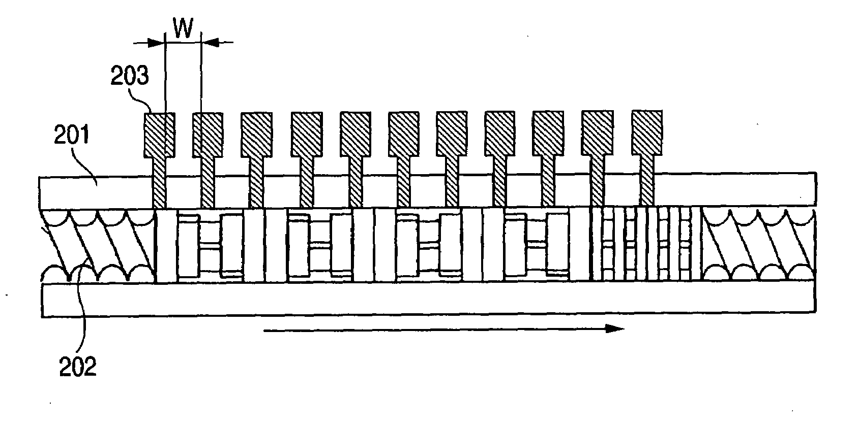
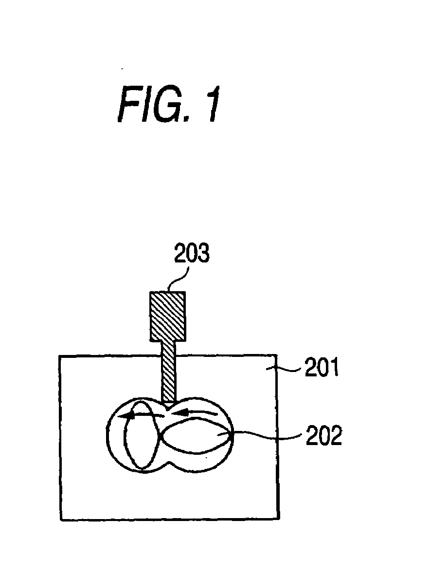
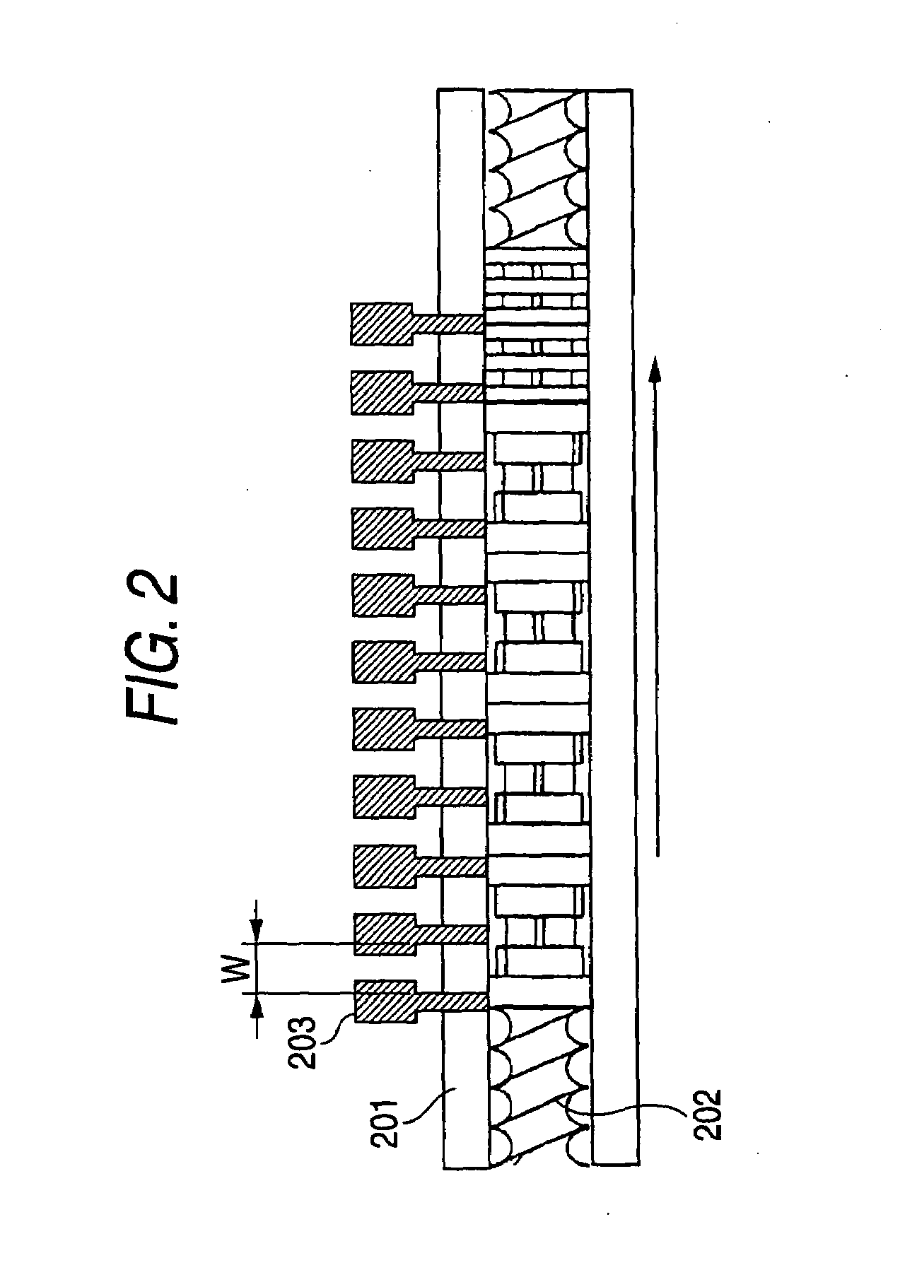
[0069]FIG. 1 shows installation positions of pressure indicators in a cross section direction of the screw shaft. FIG. 2 shows installation positions of the pressure indicators in the screw shaft direction.

[0070]Pressure indicators 203 were installed at engaging portions of twin screws 202 provided in a cylinder 201. End portions of pressure indicators 203 were inserted up to substantially the same place at the inner diameter of cylinder 201. Eleven units of the pres...

embodiment 2

[0087]In the embodiment, a resin was kneaded under the following condition, and the specific energy was obtained (energy that is supplied to a plastic material per 1 kg by the extruder) in the kneading.

[0088]Model: TEX65α-35BW-V (The Japan Steel Works Ltd.: common direction engaged twin screw extruder: cylinder inner diameter D=φ69 mm)

[0089]Material: ABS (74 wt. %)+AS (26 wt. %) compound material

[0090]ABS: φ10 mm×2 mm in thickness, flake form

[0091]AS: pellet form

[0092]Operation condition: process quantity Q=900 kg / h and screw revolution Ns=390 rpm

[0093]Cylinder temperature setting for the plasticization kneading portion: 200° C.

[0094]Screw Shape:

[0095]FIGS. 7, 8 and 9 show configurations of the plasticization kneading portion of the screw used in the embodiment.

[0096]FIG. 7 is a side view of the screw using a kneading wing of related art. The screw shown in FIG. 7 is named as a No. 4 screw.

[0097]Five sets of the FK are arranged such that the width of apiece of disk B is 0.3 times th...

embodiment 3

[0106]In the embodiment, a resin was kneaded under the following condition, and the dispersion property of titanium oxide was studied in the kneading.

[0107]Model: TEX44α-42BW-2V (The Japan Steel Works Ltd.: common direction engaged twin screw extruder: cylinder inner diameter D=φ47 mm), which is substantially the same structure as that of the plasticization kneading extruder shown in FIGS. 15A and 15B.

[0108]Material: LDPE (40 wt. %)+titanium oxide (60 wt. %) compound material

[0109]LDPE: pellet form

[0110]Titanium oxide: powder form (Titanium oxide was supplied to the molten material transporting portion from the side feeder after LDPE was melted.)

[0111]Operation condition: process quantity Q=200 kg / h and screw revolution Ns=300 rpm

[0112]Cylinder temperature setting for the molten kneading dispersion portion (second kneading portion): 100° C.

[0113]Screw Configuration:

[0114]FIG. 12 and FIG. 13 show the screw configuration of the molten kneading dispersion portion (second kneading porti...


PUM

PropertyMeasurementUnit
helix angleaaaaaaaaaa
phase angleaaaaaaaaaa

Abstract

Twist kneading disks are arranged such that the width of a piece of disk is 0.1 to 0.5 times the cylinder inner diameter D, a helix angle θ as an angle between a vertex of the front surface side of the disk and vertex of the rear surface side of the disk at the tip portion is in a range of 0°<θ<90° in the reverse rotating direction of the screws as viewed from a cross section of the disk in the end direction of the screw shaft, and a phase angle E as an angle in correlation between the disks around the screw shaft is in a range of 0°<E<90°. The twist kneading disks are incorporated in the plasticization kneading portion at the length of more than 1.88 times the cylinder inner diameter D.

Description

[0001]This application claims priority from Japanese Patent Application No. 2006-066025, filed on Mar. 10, 2006, the entire subject matter of which is incorporated herein by reference.BACKGROUND OF THE INVENTION[0002]1. Field of the Invention[0003]The present invention relates to a kneading extruder, which is suitably applicable to a plasticization kneading extruder for plastic material.[0004]2. Description of the Related Art[0005]One example of a plasticization kneading extruder for plastic material of related art is shown in FIG. 14. Twin screws 2 are provided in a cylinder 1 capable of heating and cooling. The screws 2 are coupled with a decelerator 4 and driven in the same rotating direction by a motor 3 coupled to the decelerator 4. The twin screws 2 are engaged with each other. The cylinder 1 has a feed port 5, a first vent 6a and a discharge port 7, which are placed in the order from the upstream of the cylinder 1. The screws 2 are configured by a solid transporting portion 8...

Claims


Application Information

Patent Timeline
Patent Type & Authority Applications(United States)
IPC IPC(8): B29B7/48B29C48/395B29C48/50B29C48/58B29C48/67
CPCB29B7/483B29C47/0009B29C47/38B29C47/6056B29C47/60B29C47/6031B29C47/402B29C48/03B29C48/395B29C48/402B29C48/54B29C48/57B29C48/67B29B7/726B29C48/405B29C48/40B29B7/489B29C48/58B29B7/826B29B7/481
Inventor TAKAMOTO, SEIJIINOUE, SHIGEKIISHIBASHI, MASAMICHI
Owner JAPAN STEEL WORKS LTD
Why Eureka
Try Eureka