Method and system for enhanced lithographic alignment

a technology of enhanced lithography and alignment, applied in the field of enhanced lithographic alignment, can solve the problems of reducing the usefulness of such hard masks for advanced device patterning, and achieve the effect of easy image processing

Inactive Publication Date: 2007-09-13
ASML NETHERLANDS BV
View PDF2 Cites 8 Cited by
  • Summary
  • Abstract
  • Description
  • Claims
  • Application Information

AI Technical Summary

Benefits of technology

[0020] In one embodiment of this invention, a method for alignment mark preservation includes a step of preparing a lower alignment mark structure on a substrate. In one configuration of the invention, the alignment mark structure includes a mark trench. In a further step, a hard mask coating is applied to a substrate that includes the alignment marks. Preferably, the hard mask material is an amorphous carbon material. Preferably, the hard mask material coating covers one or more substrate regions containing alignment mark features. In a further step, a selected portion of the hard mask located above the lower alignment mark structure is exposed to a dose of radiation. In one aspect of this invention, the selected portion is determined by providing a mask that selectively passes the radiation onto substrate regions that contain the alignment marks. Preferably, the radiation is visible wavelength radiation or UV radiation, the latter being generated, for example, by an excimer laser source. Preferably, the dose of radiation is sufficient to substantially graphitize the hard mask coating in regions of the substrate that are exposed to the radiation dose. In one aspect of the invention, the surface of regions of the hard mask coating that receive the dose of radiation become elevated with respect to other regions of the hard mask surface. Accordingly, the irradiated hard mask regions retain an elevated topography that can be more easily imaged in an alignment tool, such as an optical alignment system. For those elevated regions of the hard mask that are aligned with an underlying alignment mark structure, the elevated regions can serve as an alignment mark that preserves the original horizontal position of the underlying alignment mark. Accordingly, an alignment that may be partially or completely obscured by a hard mask deposition process, can be subsequently resurrected.
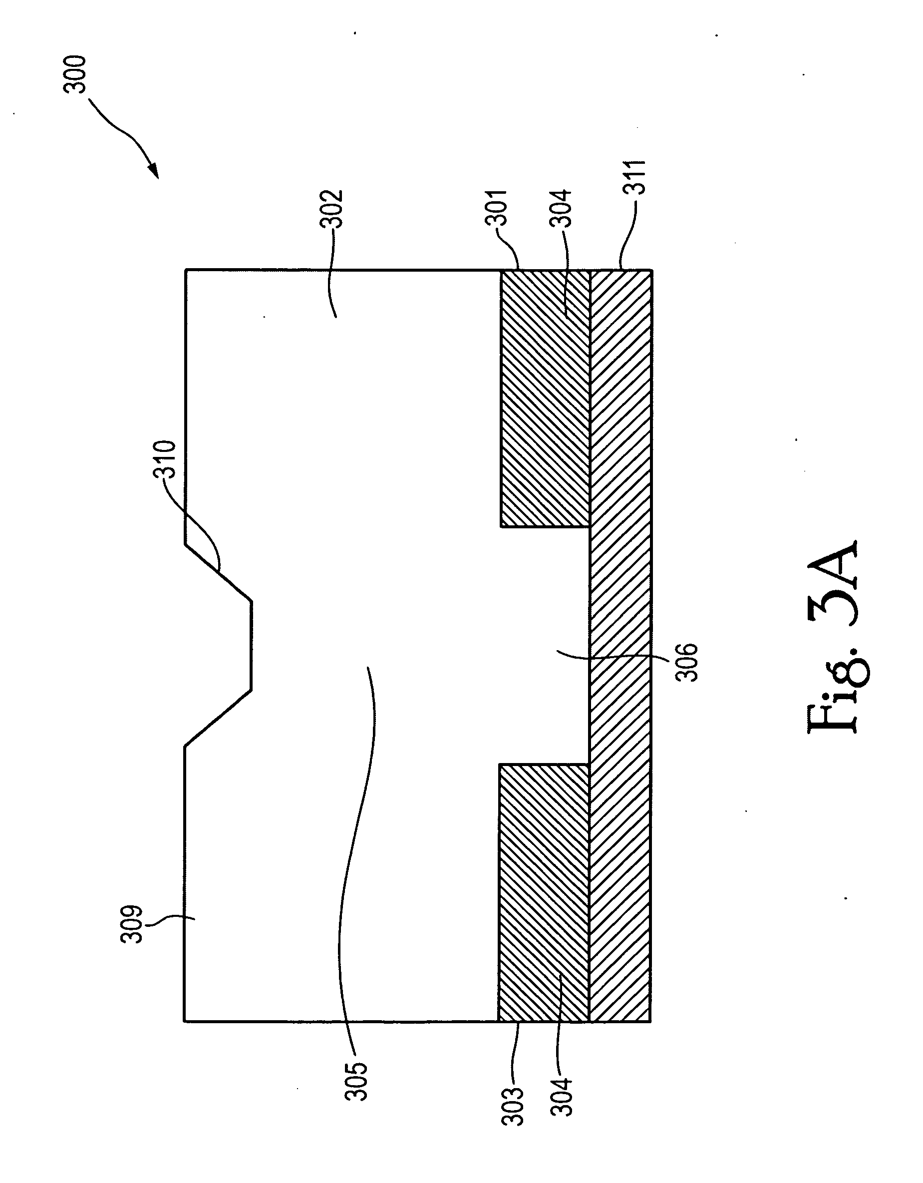
[0021] In one embodiment of the present invention, a self-aligned process for preserving an alignment mark structure includes a first step of defining a trench region in a lower alignment mark disposed on a substrate. The trench region may include a plurality of trenches. The lower alignment mark includes a plurality of raised regions that surround and define the trenches in the trench region. In a further step, a coating layer is deposited over the trench region and raised regions of the lower alignment mark. Preferably, the thickness of the coating layer is less than a planarizing thickness, wherein the upper portion of the alignment mark coating layer retains at least one or more upper trench regions, each upper trench region positioned at the same horizontal position as a corresponding lower trench region in the lower alignment mark. A hard mask layer is provided on top of the coating layer. Preferably, the hard mask layer is an amorphous carbon material. In one embodiment, the hard mask layer is substantially planarizing, wherein the thickness of the hard mask layer is locally increased in regions above the trench regions of the lower alignment mark. A portion of the hard mask layer is exposed to a dose of radiation, wherein the dose of radiation is sufficient to substantially graphitize the hard mask layer in exposed regions. Preferably, the exposed portion of the hard mask corresponds to regions of the substrate that include the lower alignment mark. Accordingly, portions of the hard mask exposed to the dose of radiation become elevated with respect to adjacent regions of the hard mask layer, wherein the surface topography of the hard mask in the region of the lower alignment mark is sufficient to be imaged in an imaging device. Preferably, the surface of the hard mask layer is globally elevated with respect to regions outside of alignment mark regions, and also locally elevated in regions corresponding to trench features within the lower alignment mark, wherein the latter features are also imaged.
[0022] In one configuration of the present invention, a self-aligned alignment mark structure includes a lower alignment mark region and an upper alignment mark region. The lower alignment mark region includes a lower trench region formed between mesa regions. The alignment mark structure further includes a coating layer disposed over the lower trench and mesa regions of the lower alignment mark region. Preferably, the coating layer is configured to provide on its upper surface an upper trench region whose horizontal position corresponds to that of the lower trench region. In one configuration of the present invention, the upper alignment mark region contains a graphitized amorphous carbon portion. The graphitized amorphous carbon layer portion includes an elevated feature having an upper surface that is raised with respect to adjust surface regions of the amorphous carbon layer portion, and whose horizontal position substantially corresponds to the horizontal position of the lower alignment mark trench region. Preferably, the elevated feature is formed by irradiation of an amorphous carbon precursor hard mask layer disposed on the coating layer, wherein irradiated portions of the hard mask layer are selectively expanded with respect to unirradiated portions of the hard mask. Preferably, the surface topography of the hard mask in the region of the elevated feature of the upper alignment mark is sufficient to be imaged in an imaging device. Preferably, the surface of the hard mask layer is globally elevated with respect to regions outside of alignment mark regions, and also locally elevated in regions corresponding to trench features within the lower alignment mark, wherein the latter features are also imaged.

Problems solved by technology

However, hard mask layers such as amorphous carbon can prevent or reduce the ability to image alignment marks, thus reducing the usefulness of such hard masks for advanced device patterning.

Method used


Image

  • Method and system for enhanced lithographic alignment
  • Method and system for enhanced lithographic alignment
  • Method and system for enhanced lithographic alignment

Examples


Embodiment Construction

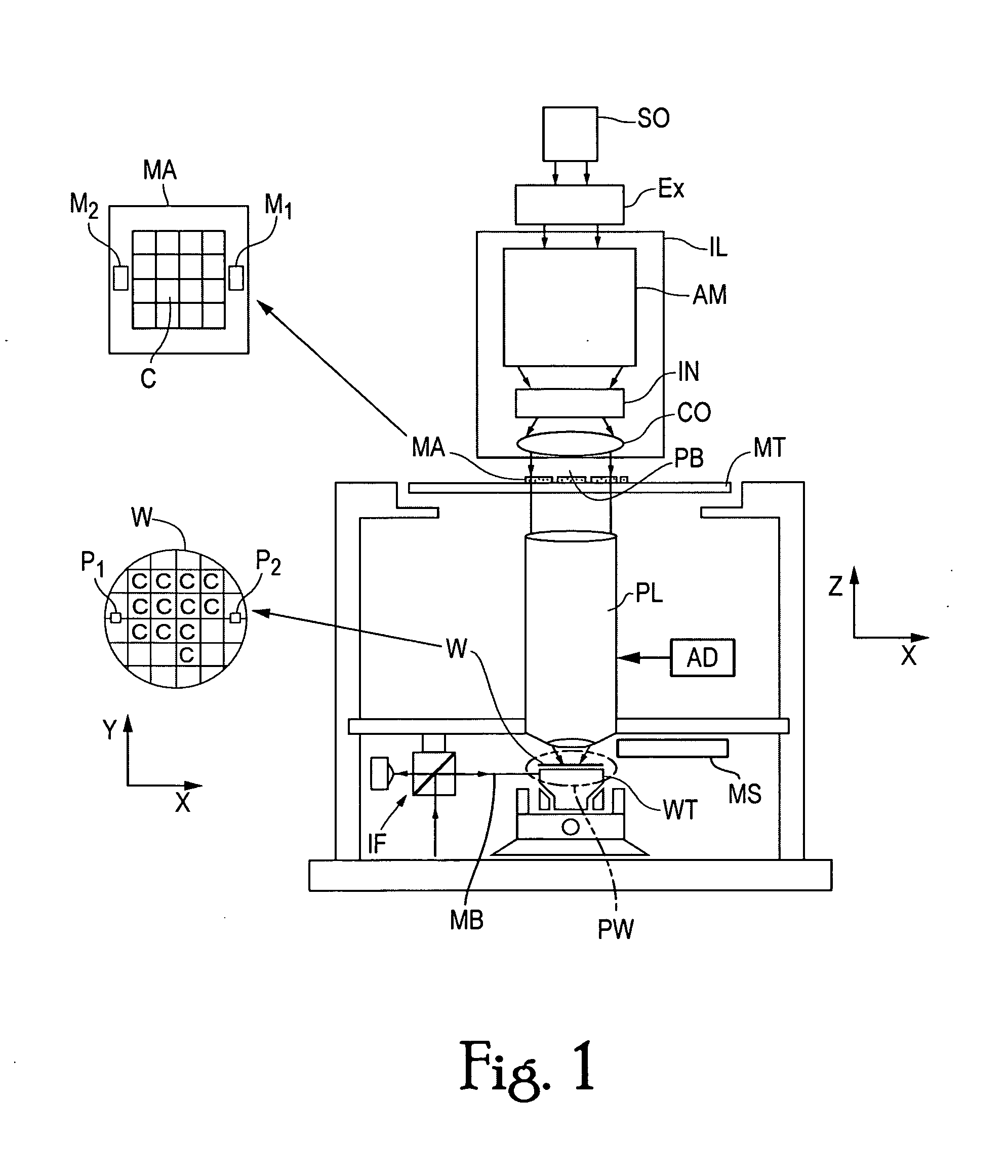
[0028]FIG. 1 schematically depicts lithographic projection apparatus that includes at least one marker structure in accordance with an embodiment of the invention. The apparatus includes:

[0029] an illumination system IL for providing a projection beam PB of radiation (e.g. UV or EUV radiation). In this particular case, the radiation system also includes a radiation source SO;

[0030] a first support structure MT (e.g. a mask table) for supporting a patterning device, MA (e.g. a mask) and connected to a first positioner (not shown) for accurately positioning the patterning device with respect to item PL;

[0031] a second support structure WT (e.g. a wafer table) for holding a substrate, W (e.g. a resist-coated silicon wafer) and connected to a second positioner PW for accurately positioning the substrate with respect to item PL; and

[0032] a projection system PL (e.g. a reflective projection lens) for imaging a pattern imported to the projection beam PB by patterning device MA onto a ...


PUM

PropertyMeasurementUnit
thicknessaaaaaaaaaa
heightaaaaaaaaaa
wavelengthaaaaaaaaaa

Abstract

A method for alignment mark preservation includes a step of preparing a lower alignment mark structure on a substrate. In one configuration of the invention, the alignment mark structure includes a lower trench. In a further step, a hard mask coating is applied to a substrate that includes the alignment marks. Preferably, the hard mask material is an amorphous carbon material. In a further step, a selected portion of the hard mask located above the lower alignment mark structure is exposed to a dose of radiation. In one aspect of the invention, the surface of regions of the hard mask coating that receive the dose of radiation become elevated with respect to other regions of the hard mask surface. For those elevated regions of the hard mask that are aligned with an underlying alignment mark trench, the elevated regions serve as an alignment mark that preserves the original horizontal position of the underlying alignment mark.

Description

FIELD OF THE INVENTION [0001] The invention relates to a system and method of enhancing alignment in lithographic systems. The invention also relates to use of a hard mask system for improving alignment processes. BACKGROUND OF THE INVENTION [0002] The invention is directed to the field of lithography and lithographic projection apparatus that encompass a radiation system for supplying a projection beam of radiation, a support structure for supporting a patterning device, which serves to pattern the projection beam according to a desired pattern, a substrate table for holding a substrate; and, a projection system for projecting the patterned beam onto a target portion of the substrate. [0003] The term “patterning device” as employed here should be broadly interpreted as referring to devices that can be used to endow an incoming radiation beam with a patterned cross-section, corresponding to a pattern that is to be created in a target portion of the substrate. The term “light valve” ...

Claims


Application Information

Patent Timeline
Patent Type & Authority Applications(United States)
IPC IPC(8): G03C5/00G03F9/00H01L23/544
CPCG03F9/7076G03F9/708H01L2223/54453H01L21/3105H01L23/544G03F9/7084H01L2924/0002Y10S438/975H01L2924/00H01L2223/54426
Inventor LALBAHADOERSING, SANJAYSINGHMUSA, SAMI
Owner ASML NETHERLANDS BV
Why Eureka
Try Eureka