Laser system for photonic excitation investigation

a laser system and excitation technology, applied in the field of laser systems for use in photonic excitation investigation, can solve the problems of difficult to achieve wavelength switching with a solid state laser, large and expensive solid state laser, and limited application of two-photon microscopy

Inactive Publication Date: 2007-09-20
UNIVERSITY OF KANSAS
View PDF6 Cites 21 Cited by
  • Summary
  • Abstract
  • Description
  • Claims
  • Application Information

AI Technical Summary

Benefits of technology

[0008] The present invention overcomes the above-discussed and other problems in the prior art by providing an improved laser system for use in photonic excitation investigation of a target object. In one embodiment, the laser system comprises a pulsed fiber laser and a non-linear photonic crystal fiber, wherein the photonic crystal fiber allows for switching, or tuning, the wavelength of the laser beam prior to providing it to an instrument for photonically exciting the target object. The target object absorbs the incident photons, and emits a corresponding photon which is detected and used to generate an image of the target object.

Problems solved by technology

Unfortunately, applications for two-photon microscopy have been limited by the requirement of using a relatively large and expensive solid state laser, such as a Ti:Sapphire laser, as the source of excitation photons.
Furthermore, wavelength switching with a solid state laser requires mechanical realignment of the laser and can be difficult to accomplish.
Unfortunately, CARS imaging and spectroscopy require the use of two different and expensive laser sources, such as two Ti:Sapphire lasers, which must be stringently synchronized and maintained.
Such synchronization is particularly difficult because the widths of the optical pulses are on the order of 100 femtoseconds, i.e., 100×10−15 seconds.

Method used


Image

  • Laser system for photonic excitation investigation
  • Laser system for photonic excitation investigation
  • Laser system for photonic excitation investigation

Examples


Embodiment Construction

.

BRIEF DESCRIPTION OF THE DRAWING FIGURES

[0012] The present invention is described herein with reference to the following drawing figures, with greater emphasis being placed on clarity rather than scale:

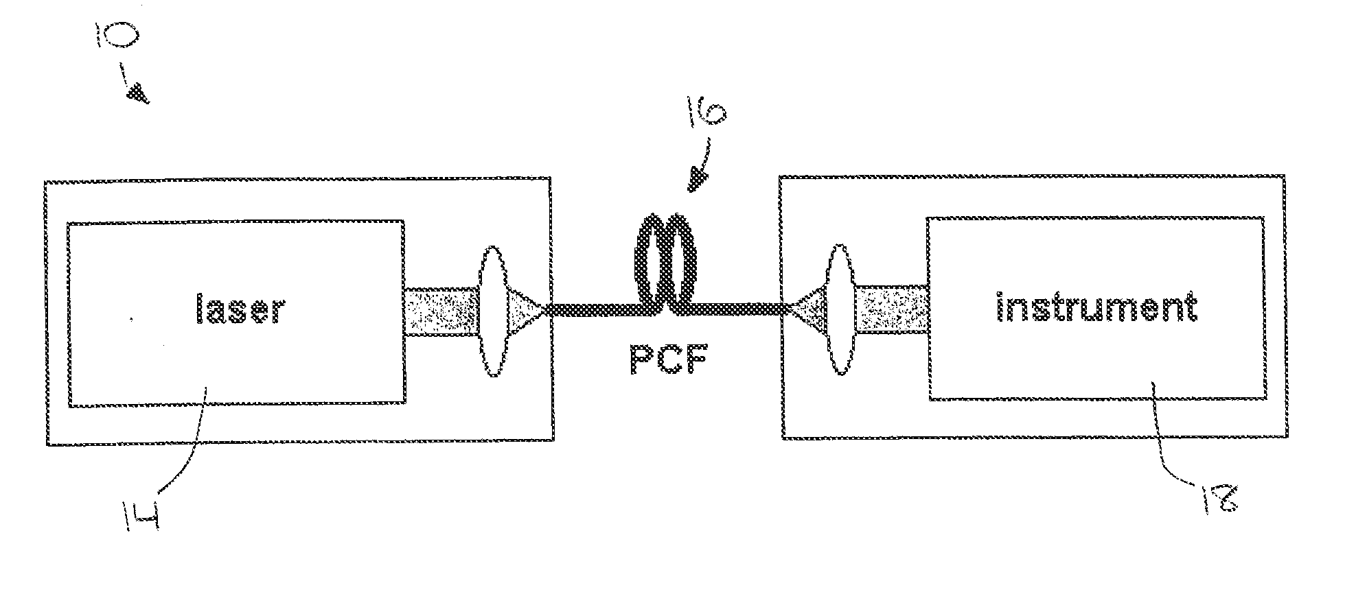
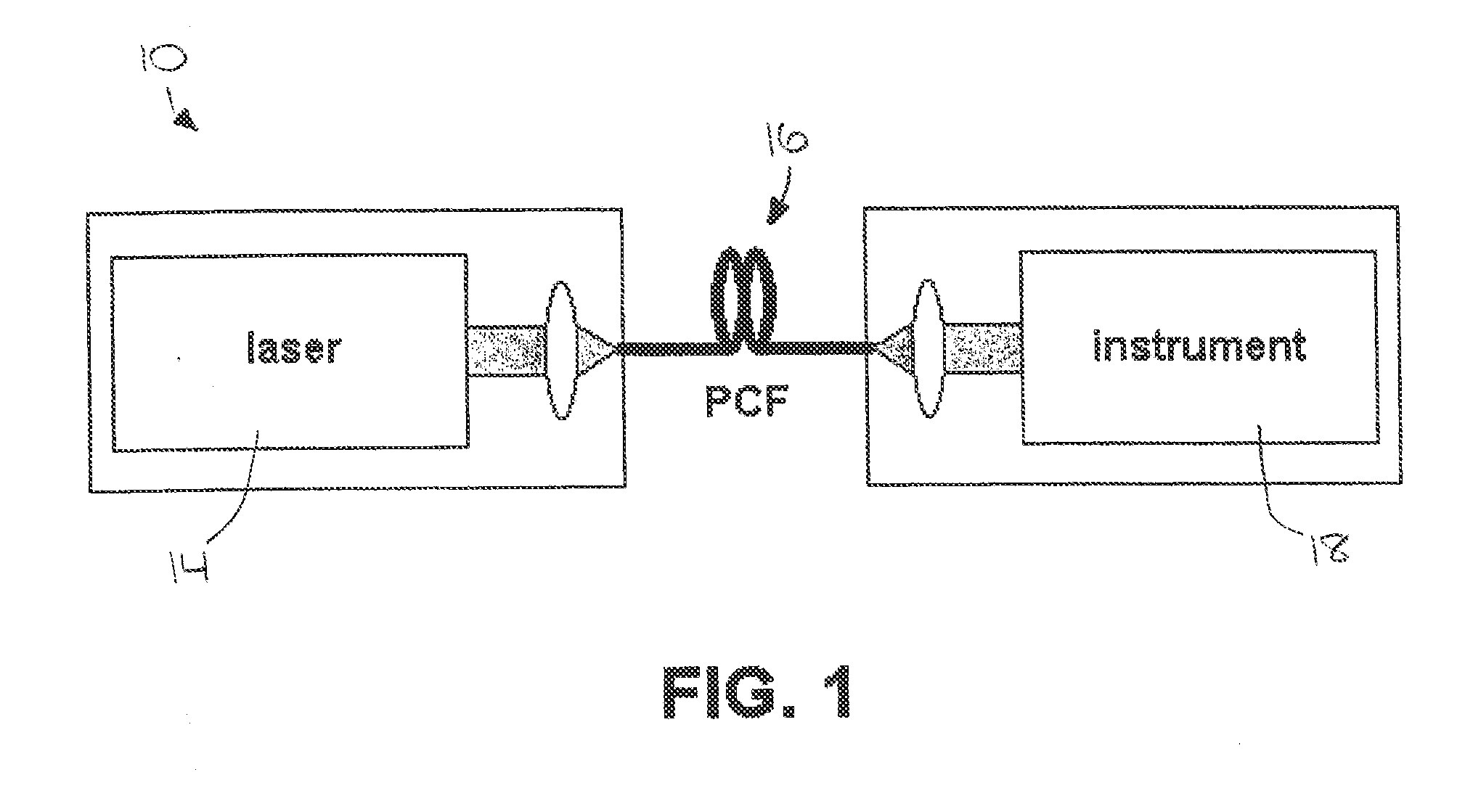
[0013]FIG. 1 is a high-level diagram of an embodiment of the laser system of the present invention connected to a photonic excitation investigation instrument;

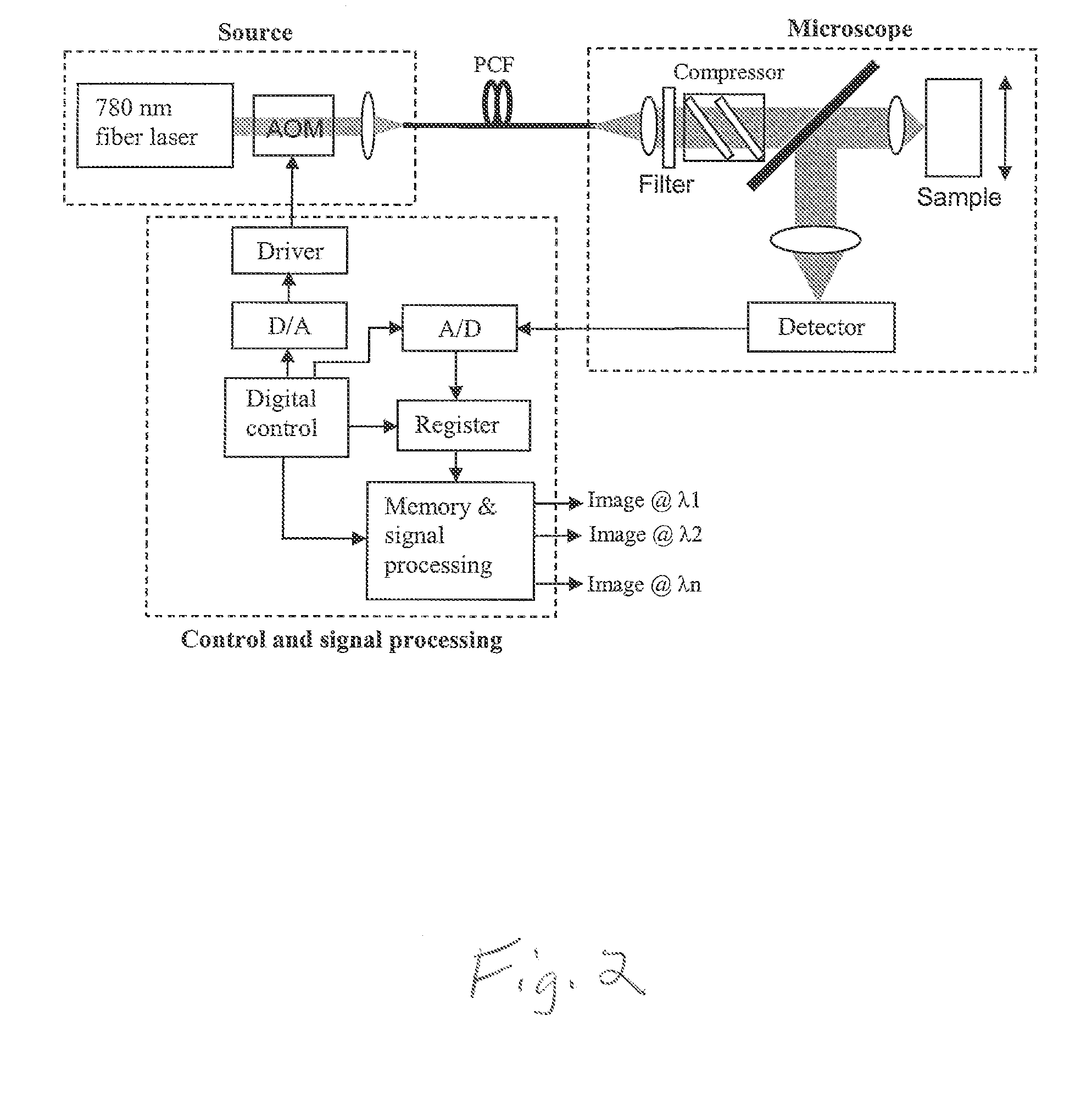
[0014]FIG. 2 is a high-level diagram of an embodiment of the laser system incorporated into a two-photon excitation microscopy system;

[0015]FIG. 3 is a plot of power spectral density versus soliton wavelength, evidencing soliton wavelength shift created by an embodiment of the laser system of FIG. 1;

[0016]FIG. 4 is a collection of two-photon fluorescence images with two-photon excitation wavelengths from 850 nm to 1100 nm;

[0017]FIG. 5 is a single two-photon fluorescence image which combines two images from FIG. 4 with two-photon excitation wavelengths at 1000 nm and 1100 nm, respectively;

[0018]FIG. 6 is a plot of fluores...


PUM

PropertyMeasurementUnit
poweraaaaaaaaaa
poweraaaaaaaaaa
wavelengthaaaaaaaaaa

Abstract

A laser system (10) for use in photonic excitation investigation of a target object, in which the target object interacts with incident photons and emits a corresponding photon which is detected and used to generate an image of the target object. The laser system (10) includes a pulsed fiber laser (14) for producing a laser beam, and a non-linear photonic crystal fiber (16) for carrying the laser beam from the laser (14) to an instrument (18) for photonically exciting the target object. The photonic crystal fiber (16) allows for switching, or tuning, the wavelength of the laser beam. In two-photon microscopy, the laser system (10) allows for providing multiple wavelengths for exciting a plurality of different fluorophores simultaneously. In coherent Raman imaging and spectroscopy, the laser system (110) allows for using a single laser to provide two laser beams of different wavelengths.

Description

RELATED APPLICATIONS [0001] The present non-provisional patent application claims priority benefit of an earlier-filed provisional patent application titled “Wavelength Tunable Femtosecond Laser Source for Two-Photon Biological Imaging and Correlated Antistocks Raman Spectrosco”, Ser. No. 60 / 783,010, filed Mar. 16, 2006. The identified earlier-filed application is hereby incorporated by reference into the present application.FIELD OF THE INVENTION [0002] The present invention relates to laser systems for use in photonic excitation investigation, particularly microscopy and spectroscopy, of a target object. More specifically, the present invention concerns such a laser system comprising a pulsed fiber laser and a non-linear photonic crystal fiber, wherein the photonic crystal fiber allows for switching, or tuning, the wavelength of the laser beam, for use in, for example, two-photon microscopy and coherent Raman imaging and spectroscopy, including Coherent Anti-Stokes Raman Scatterin...

Claims


Application Information

Patent Timeline
Patent Type & Authority Applications(United States)
IPC IPC(8): G01N21/64
CPCG01N21/6458G01N2021/653G01N21/65
Inventor HUI, RONGQINGJOHNSON, CAREY K.
Owner UNIVERSITY OF KANSAS
Why Eureka
Try Eureka