
Spark plug for use in an internal-combustion engine

a technology for combustion engines and spark plugs, which is applied in the manufacture of spark plugs, electric discharge tubes, and discharge tubes/lamp details. it can solve the problems of deteriorating heat sinking ability (heat dispersion) of ground electrodes, affecting the inflow of air-fuel mixture to the spark discharge gap, and affecting the ignitability of spark plugs. it achieves better thermal conductivity, reduces the width of the gap, and improves the effect of thermal conductivity

Active Publication Date: 2007-09-20
NGK SPARK PLUG CO LTD
View PDF10 Cites 30 Cited by
  • Summary
  • Abstract
  • Description
  • Claims
  • Application Information

AI Technical Summary

Benefits of technology

[0008]Hereinafter, suitable compositions for solving the above-mentioned problems will be described in accordance with a topic. It is noted that an appropriate effect of the invention will be added to a corresponding composition if needed.
[0009]Composition 1. A spark plug according to this composition is comprised of: a center electrode; an insulator provided so as to cover the surroundings of the center electrode; a cylindrical metal shell provided so as to cover the surroundings of the insulator; a ground electrode so disposed that one end thereof is joined to a front-end face of the metal shell and the other end thereof faces the front-end face of the center electrode; and a spark discharge gap formed between the front-end face of the center electrode and a front-end portion of the ground electrode, wherein the ground electrode is constituted so as to reduce its width toward a back face thereof, which is opposed to the center electrode side, at least in a front-end portion thereof located at a front-end side from a center of the spark discharge gap, wherein at least a portion of the ground electrode where sparks are discharged has an outer layer made of a nickel alloy and an inner layer made of pure copper or a copper alloy having a better thermal conductivity than that of the outer layer, and wherein a ratio of a cross-sectional area of the inner layer to the entire cross-sectional area of the ground electrode is 10% or more to 35% or less.
[0010]Composition 2. A spark plug according to this composition is comprised of: a center electrode; an insulator provided so as to cover the surroundings of the center electrode; a cylindrical metal shell provided so as to cover the surroundings of the insulator; a ground electrode so disposed that one end thereof is joined to a front-end face of the metal shell and the other end thereof faces the front-end face of the center electrode; and a spark discharge gap formed between the front-end face of the center electrode and a front-end portion of the ground electrode, wherein the ground electrode has a width of 2 mm or less at least in the front-end portion thereof located at a front-end side from a center of the spark discharge gap and a convex-shaped curved face at a back face thereof located opposed to the center electrode side, wherein at least a portion of the ground electrode where sparks are discharged has an outer layer made of a nickel alloy and an inner layer made of pure copper or a copper alloy having a better thermal conductivity than that of the outer layer, and wherein a ratio of a cross-sectional area of the inner layer to the entire cross-sectional area of the ground electrode is 10% or more to 35% or less.
[0011]It is noted that a noble metal tip may be provided on at least either the ground electrode or the center electrode. When a noble metal tip is provided only on the center electrode, the spark discharge gap is formed between the noble metal tip and the ground electrode which are opposed to each other. When a noble metal tip is formed only on the ground electrode, the spark discharge gap is formed between the noble metal tip and the center electrode which are opposed to each other. When a noble metal tip is provided on both the ground electrode and the center electrode, the spark discharge gap is formed between the noble metal tips which are opposed to each other. On the other hand, when no noble metal tip is provided on the center electrode or the ground electrode, the spark discharge gap is formed between the front-end face of the center electrode and an inner side face of the ground electrode which are opposed to each other.
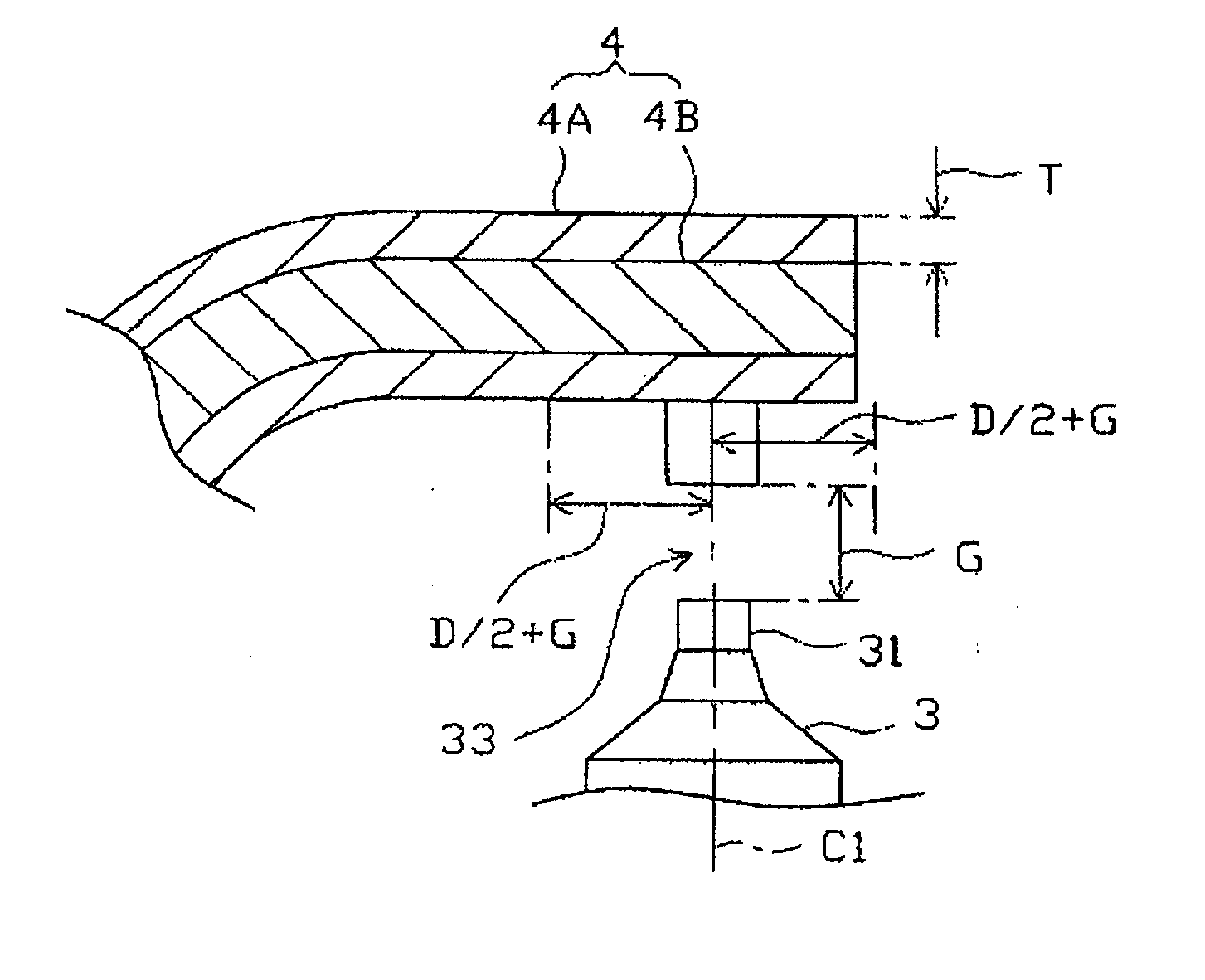
[0012]Further, the ground electrode does not necessary assume a circular form in the cross-section, but may be constituted so as to reduce its width toward the back face thereof, which is opposed to the center electrode side, at least in the front-end portion thereof located at the front-end side from the center of the spark discharge gap. Thus, the convex-shaped curved face may be formed at the back face of the ground electrode which is opposed to the center electrode side. When the ground electrode is constituted to have such a reduced width at least at the back face thereof, an air-fuel mixture is likely to flow into the inner side of the ground electrode whereby the air-fuel mixture can easily reaches the spark discharge gap. Further, in a conventional ground electrode assuming a rectangular form in the cross-section, “reduced width” means that it is not a constitution where a corner of the ground electrode is simply chamfered, but a constitution where ¼ or more of the width is reduced along a direction perpendicular to the width (i.e., a thickness of the ground electrode).
[0013]Further, a “width” referred to in this document means a width in a direction perpendicular to the longitudinal direction of the spark plug (i.e., the direction parallel to the front-end face of the metal shell) and is a projection width when the ground electrode is viewed from the center electrode (the front-end face of the ground electrode). Furthermore, a “copper alloy” in this document is an alloy containing over 50% by mass of copper.

Problems solved by technology

When the spark plug is mounted such that an air-fuel mixture is exposed to a back face of the ground electrode, there is a possibility that the inflow of the air-fuel mixture to the spark discharge gap may be disturbed by the ground electrode.
As a result, the ignitability of the spark plug is unlikely to be stable.
As a result, so-called heat sinking ability (heat dispersion) of the ground electrode deteriorates, and the temperature thereof tends to increase at the time of high speed driving or the like.
Consequently, the ground electrode suffers considerable erosion which leads to a poor durability thereof.
However, when the materials constituting the outer layer and the inner layer differ, a deformation (i.e., “spring back”) of the ground electrode tends to occur due to a difference in the coefficient of thermal expansion between the outer layer and the inner layer, thereby possibly influencing the spark discharge gap.
Specifically, a defect of the spark plug caused by such deformation is likely to occur when an outer diameter of the ground electrode is relatively small (e.g., 2 mm or less).

Method used


Image

  • Spark plug for use in an internal-combustion engine
  • Spark plug for use in an internal-combustion engine
  • Spark plug for use in an internal-combustion engine

Examples


first embodiment

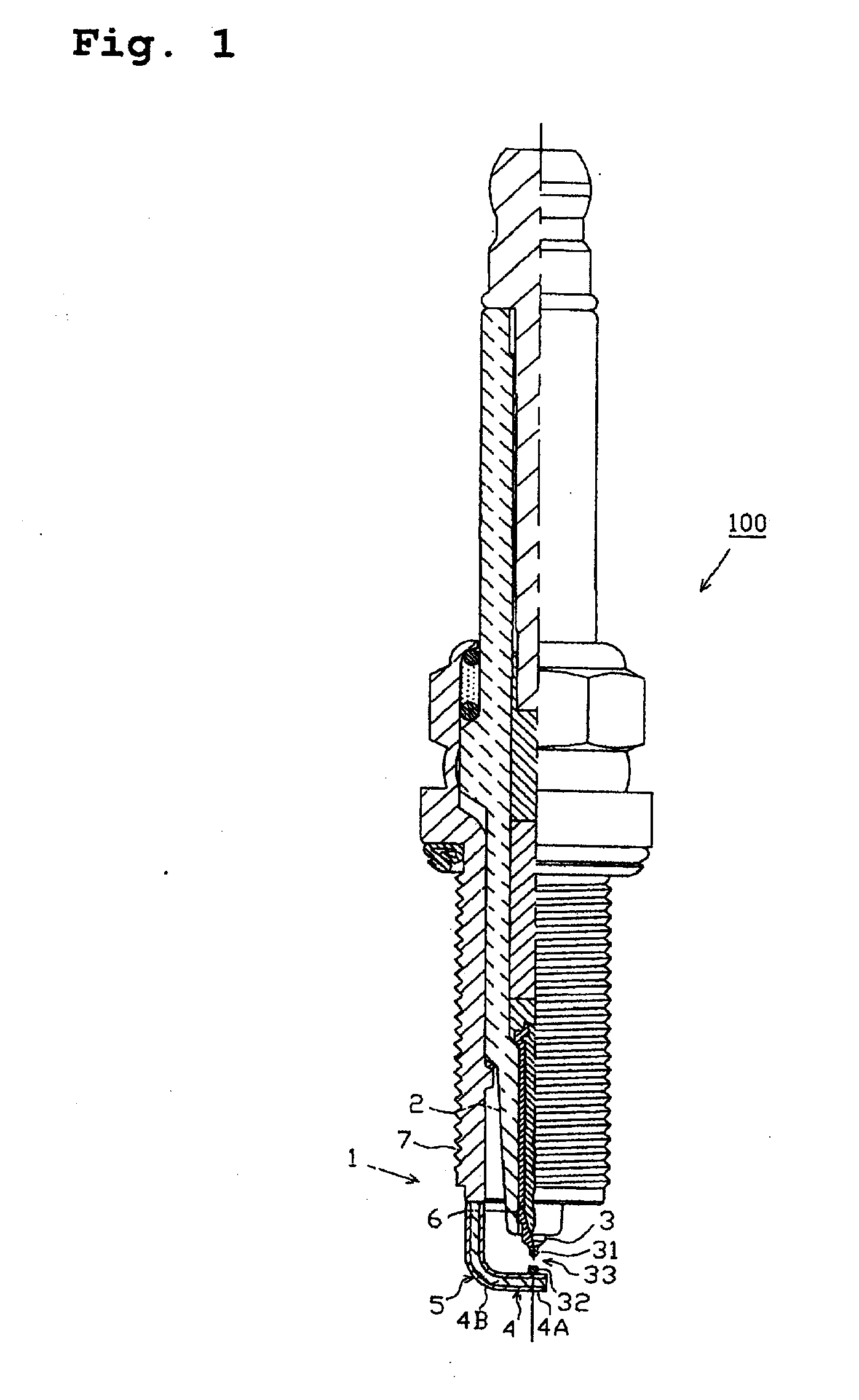
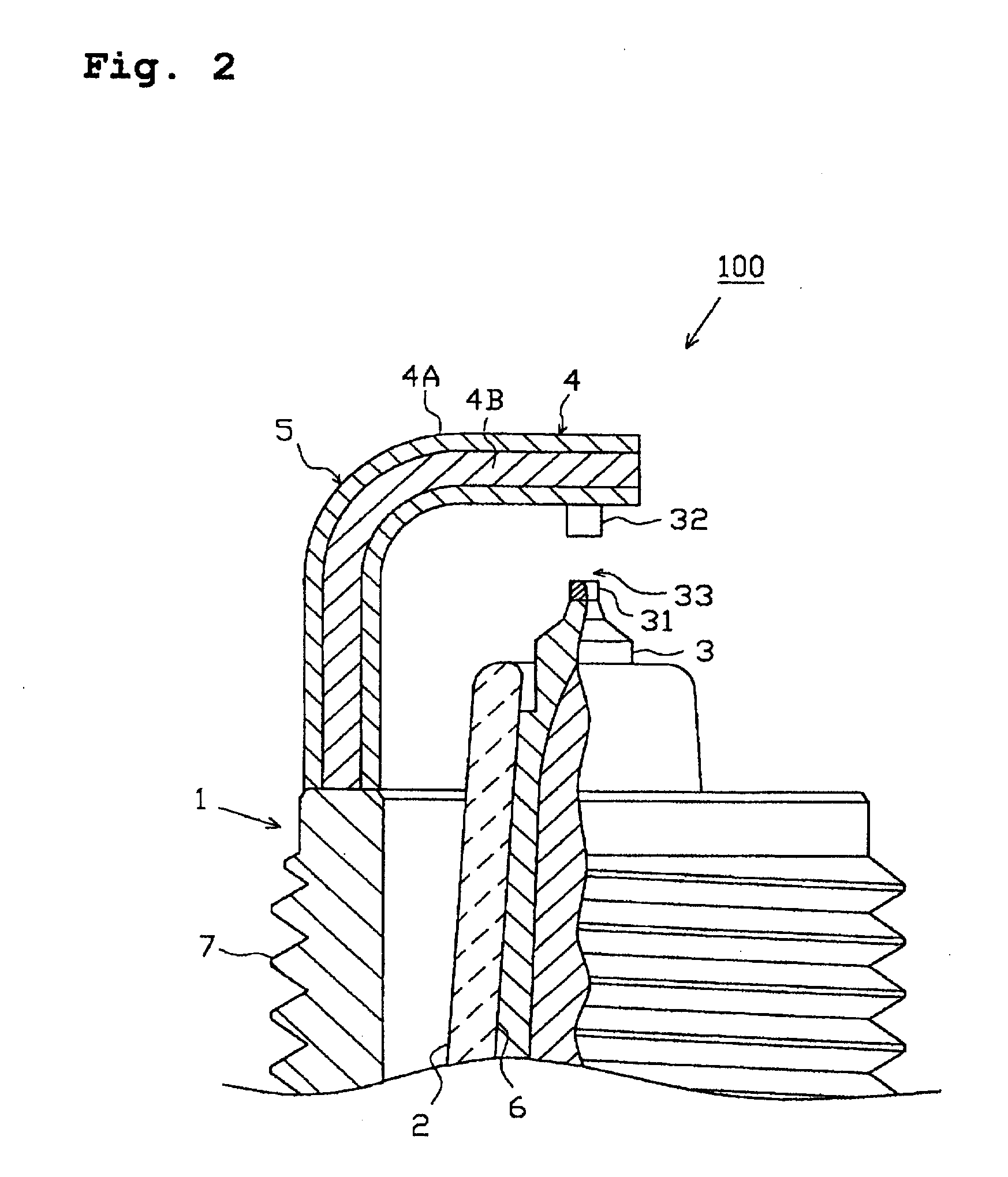
[0043]the present invention will be described with reference to the drawings. FIG. 1 is a partially sectional front view showing an entire composition of a spark plug according to this embodiment, and FIG. 2 is a partially sectional front view showing a composition of a main portion. Hereinafter, the present invention will be described with reference to mainly FIG. 2.

[0044]As shown in FIG. 2 or the like, a spark plug 100 according to this embodiment is comprised of a metal shell 1, an insulator 2, a center electrode 3 and a ground electrode 4. There is also provided a contact terminal or the like electrically connected to the center electrode 3 through a resistor or a glass seal portion at a rear-end side of the insulator 2, even though no numeral is particularly attached thereto. The metal shell 1 assumes a cylindrical form and holds the insulator 2 therein through talc, a packing or the like. A front-end portion of the insulator 2 projects from the metal shell 1. The center electr...

second embodiment

[0071]The ground electrode 4 also assumes a circular form in the cross-section and an outer diameter L [i.e., the width in the direction perpendicular to the longitudinal direction of the spark plug 100 (the direction parallel to the front-end face of the metal shell) which is a projection width when the ground electrode 4 is viewed from the center electrode 3 (front-end face of the ground electrode 4)] thereof is 2 mm or less (e.g., 1.7 mm).

[0072]Further, the ratio of the cross-sectional area of the inner layer 4B to the entire cross-sectional area of the ground electrode 4 is set to be 20% or more (e.g., 25% in this embodiment). However, although there is no particular limitation with respect to the maximum ratio of the cross-sectional area, a thickness T (refer to FIG. 5B) of the outer layer 4A is set to be 0.2 mm or more.

[0073]In the second embodiment, provided that the distance between a point P2 nearest to the center electrode 3 in the outer layer 4A and a point P1 nearest to...


PUM


Abstract

A spark plug 100 comprised of a metal shell 1, an insulator 2, a center electrode 3 and a ground electrode 4. A rear-end face of the ground electrode 4 is welded to a front-end face of the metal shell 1, and a bent portion 5 located at the intermediated position in the longitudinal direction is bent toward the center of the spark plug 100. The ground electrode 4 assumes a circular-shape with a diameter of 2 mm or less whereby an inflow of an air-fuel mixture is not disturbed even when the air-fuel mixture directly flows into a back face of the ground electrode 4. The ground electrode 4 is comprised of an outer layer 4A made of a nickel alloy and an inner layer 4B made of pure copper with an excellent thermal conductivity, in which a ratio of a cross-sectional area of the inner layer 4B to the entire cross-sectional area of the ground electrode 4 is 10% or more to 35% or less. Thus, the spark plug 100 which is excellent in heat sinking ability and can prevent a spring back phenomenon due to a difference in a coefficient of thermal expansion.

Description

FIELD OF THE INVENTION [0001]The present invention relates to a spark plug for use in an internal-combustion engine.BACKGROUND OF THE INVENTION [0002]A spark plug for use in internal-combustion engines, such as the engine of an automobile includes, for example, a center electrode, an insulator provided outside thereof, a cylindrical metal shell disposed outside of said insulator and a ground electrode whose rear portion is joined to a front-end face of said metal shell. The ground electrode assumes a generally rectangular form in the cross-section and is disposed so that a front-end portion inner side face thereof faces the front-end face of the center electrode. Thus, a spark discharge gap is formed between the front-end portion of the center electrode and the front-end portion of the ground electrode.[0003]A screw portion (not illustrated) is formed on an outer circumferential face of the metal shell. A spark plug is mounted on an engine in such a manner that the screw portion of ...

Claims


Application Information

Patent Timeline
IPC IPC(8): H01T13/20
CPCH01T13/20H01T21/02H01T13/39H01T13/36
Inventor TORII, KAZUYOSHIYOSHIDA, KAZUMASAMATSUTANI, WATARU
Owner NGK SPARK PLUG CO LTD
Learn More