Display Panel and Method for Manufacturing same

a display panel and self-illuminating technology, applied in the direction of identification means, instruments, optics, etc., can solve the problems of low luminance, low contrast ratio, and inability to achieve the target display state, and achieve the effect of high luminan

Inactive Publication Date: 2007-09-20
SHARP KK
View PDF3 Cites 26 Cited by
  • Summary
  • Abstract
  • Description
  • Claims
  • Application Information

AI Technical Summary

Benefits of technology

[0025] With the above method, the microlens is patterned by hardening the photopolymerizing polymer with the use of light that transmits through the aperture section. This allows the microlens to be formed in a self-alignment manner with respect to the aperture section. As such, no misalignment is caused between the microlens and the pixel, or the sub-pixel. Furthermore, no misalignment is caused neither in the pitch between pixels nor in the pitch between microlenses. Therefore, no moire is generated between the pixels and the microlenses. Accordingly, the light-converging function of the microlens is sufficiently demonstrated, while no moire is generated. Therefore, it is possible to produce a display apparatus that allows displaying with high luminance.

Problems solved by technology

As a result, a targeted display state is not realized.
This causes a leakage of light during a black state, and therefore a contrast ratio decreases.
The reason therefor is that, although a pixel pitch is reduced, sizes of the TFT, the bus line and the like cannot be reduced to a smaller size than a certain size, due to constrains of electrical performance, manufacture techniques and the like.
The technique of Japanese Unexamined Patent Publication No. 109417 / 1999 (Tokukaihei 11-109417) mentioned above, however, has a problem that a display of the liquid crystal display apparatus becomes darker, and therefore visibility is degraded.
Consequently, the display of the liquid crystal display apparatus becomes darker, and therefore the visibility is degraded.
Further, the technique of Japanese Unexamined Patent Publication No. 49925 / 1997 (Tokukaihei 9-49925) mentioned above has a problem that an image contrast is degraded due to residual birefringence in the viewing-angle enlarging film 41.
This brings a problem that significant moire is generated due to misalignment between a pitch of the TN-liquid crystal cells 42 and a pitch of the convex sections d of the viewing-angle enlarging film 41.
This is, however, not sufficient as countermeasure against moire, and there may be a case where further countermeasure is required, for example, that a clearance is provided between the viewing-angle enlarging film 41 and the TN-liquid crystal cell 42.
This, however, brings a problem that the display panel becomes thicker.
For this reason, it is difficult to achieve uniformity in shape of the microlenses of the two layers.

Method used


Image

  • Display Panel and Method for Manufacturing same
  • Display Panel and Method for Manufacturing same
  • Display Panel and Method for Manufacturing same

Examples


Embodiment Construction

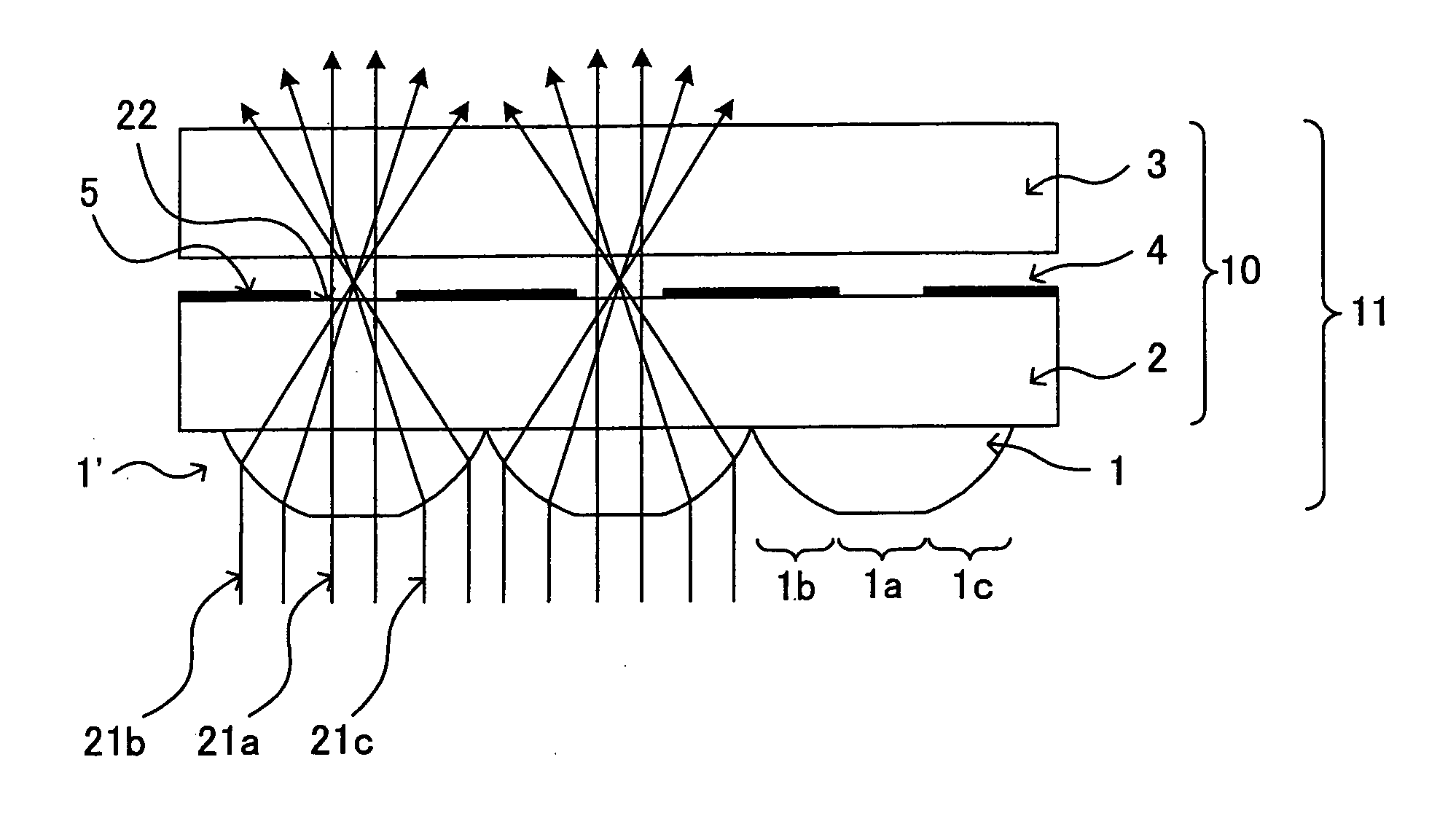
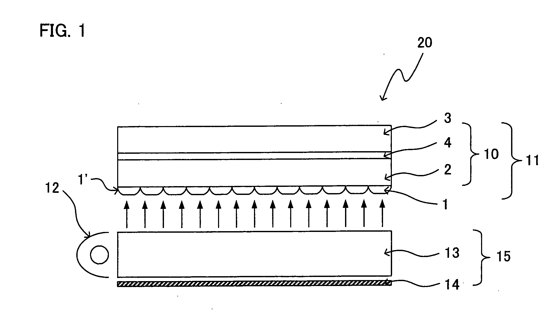
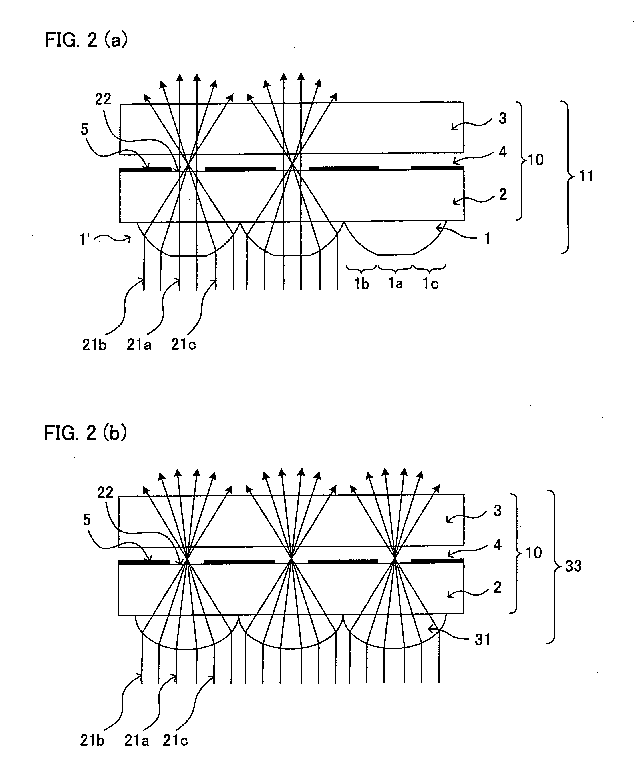
[0049] The following describes an embodiment of the present invention, with reference to figures. FIG. 1 is a cross sectional diagram schematically illustrating a main section of a liquid crystal display panel (display panel) 11, and a main section of a liquid crystal display apparatus 20 including the liquid crystal display panel 11, according to the present embodiment. Note that the liquid crystal display apparatus 20 is a transflective liquid crystal display apparatus. The reflective liquid crystal display apparatus realizes a display under dark illumination by utilizing light of backlight that transmits through a liquid crystal display panel 11 in displaying, while realizing a display under bright illumination by reflecting light that enters a display surface from the surrounding area of the liquid crystal display panel 11. Thus, the liquid crystal display apparatus 20 is a non self-illuminant type display apparatus.

[0050] As illustrated in FIG. 1, the liquid crystal display ap...


PUM

PropertyMeasurementUnit
sizeaaaaaaaaaa
tilt angleaaaaaaaaaa
refractive indexaaaaaaaaaa

Abstract

A microlens array 1′ constituted of a plurality of microlenses 1 each having a flat section 1a at a top portion is arranged on one side of a liquid crystal display panel 11 from which side light from a backlight enters. Each microlens 1 is so formed that its width is equal to the pixel pitch. Consequently, the viewing angle can be widened without deteriorating front luminance.

Description

TECHNICAL FIELD [0001] The present invention relates to a non self-illuminant type display panel and a method for manufacturing the display panel, and particularly, relates to a display panel including a microlens array that is provided to improve light utilization efficiency, and a method for manufacturing the display panel. BACKGROUND ART [0002] In recent years, liquid crystal display apparatuses, which are non self-illuminant type display apparatuses, have been widely used as display apparatuses of monitors, projectors, mobile information terminals, mobile phones and the like. A non self-illuminant type display apparatus, exemplified by a liquid crystal display apparatus, displays images and / or texts normally by causing a drive signal to change a transmissivity (or reflectivity) of the display panel to modulate an intensity of light emitted from a light source with respect to the display panel. Examples of the display apparatus includes: a direct-view type display apparatus which...

Claims


Application Information

Patent Timeline
Patent Type & Authority Applications(United States)
IPC IPC(8): G02F1/1335G02B3/00G02F1/13357G09F9/00
CPCG02B3/0031G02B3/005G02F1/133555G02F1/133526G02F1/133512
Inventor OKADA, KUNIAKINAKANISHI, HIROSHI
Owner SHARP KK
Why Eureka
Try Eureka