Substrate For Liquid Crystal Display And Liquid Crystal Display Unit

a liquid crystal display and liquid crystal technology, applied in non-linear optics, instruments, optics, etc., can solve problems such as insufficient achieve the effects of reducing defective air bubble appearance, and improving the extension of liquid crystals

Inactive Publication Date: 2007-09-20
SHARP KK
View PDF13 Cites 4 Cited by
  • Summary
  • Abstract
  • Description
  • Claims
  • Application Information

AI Technical Summary

Benefits of technology

[0039] A substrate for liquid crystal display of the invention is provided with a projection for controlling alignments of liquid crystal molecules, and usually it is employed in a MVA type liquid crystal display unit. Since such MVA type liquid crystal display unit is suitable for TV and the like with big video screen, a drop filling method is principally used as a manner for charging a liquid crystal in case of manufacturing a liquid crystal panel by the use of the substrate for liquid crystal display of the invention. The present invention attains advantageous effects for improving an extension of liquid crystal in case of charging a liquid crystal in accordance with such drop filling method. However, the present invention is also applicable for charging a liquid crystal in accordance with a pouring method, and in this case also, the invention can achieve advantageous effects for improving an extension of the liquid crystal.
[0040] A substrate for liquid crystal display of the invention is not specifically limited, but it may or may not contain constitutional elements other than that as described above so far as the substrate is constituted with the above-described constituents as its indispensable ones.
[0041] A preferred embodiment of a substrate for liquid crystal display according to

Problems solved by technology

The present inventors have found that projections for alignment control become a barrier, it results in

Method used


Image

  • Substrate For Liquid Crystal Display And Liquid Crystal Display Unit
  • Substrate For Liquid Crystal Display And Liquid Crystal Display Unit
  • Substrate For Liquid Crystal Display And Liquid Crystal Display Unit

Examples


embodiment 1

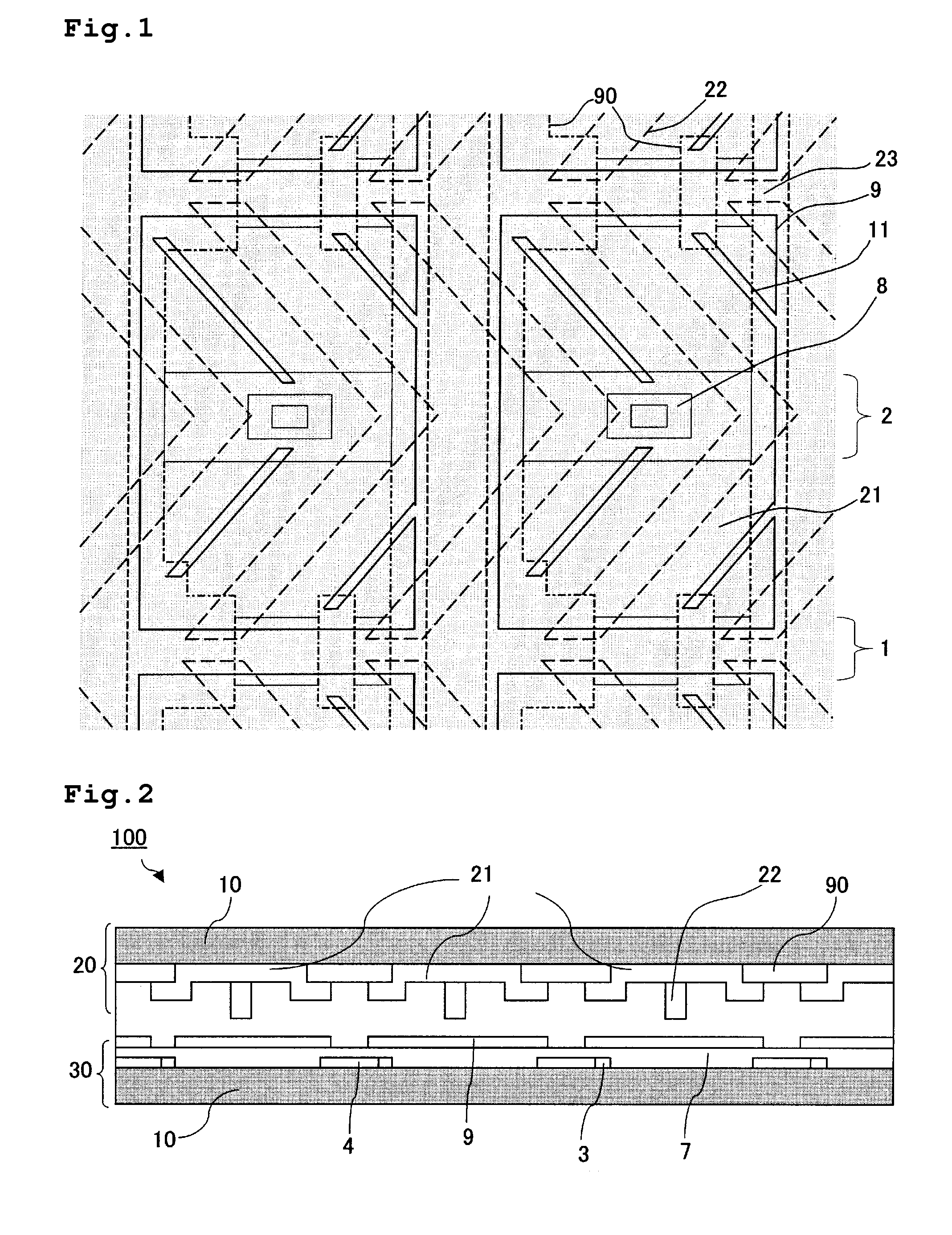
[0063]FIG. 2 is a sectional view showing schematically a liquid crystal display unit according to an embodiment 1. As shown in FIG. 2, the liquid crystal display unit 100 contains a pair of substrates (substrate for liquid crystal display) opposed to each other. And plastic beads or columnar resin structures provided on a color filter substrate 20 or the like is used as a spacer (not shown), whereby space between the substrates is maintained constant. The liquid crystal display unit 100 is an active matrix type liquid crystal display unit wherein the pair of substrates opposed to each other is composed of the color filter substrate 20 and an active matrix substrate 30 having a switching device such as a thin film transistor (hereinafter referred optionally to as “TFT”).

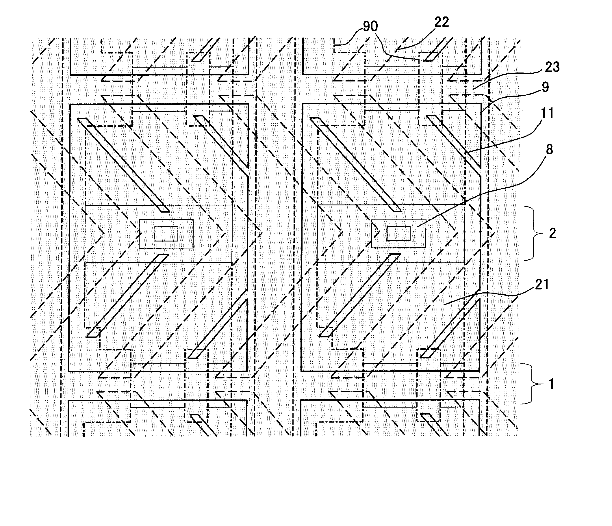
[0064]FIG. 1 is a plan view showing schematically a part (two pixels) of a liquid crystal panel according to the embodiment 1 wherein reference numeral 90 designates a black matrix (BM) and 22 an alignment control pr...

embodiments 2 to 5

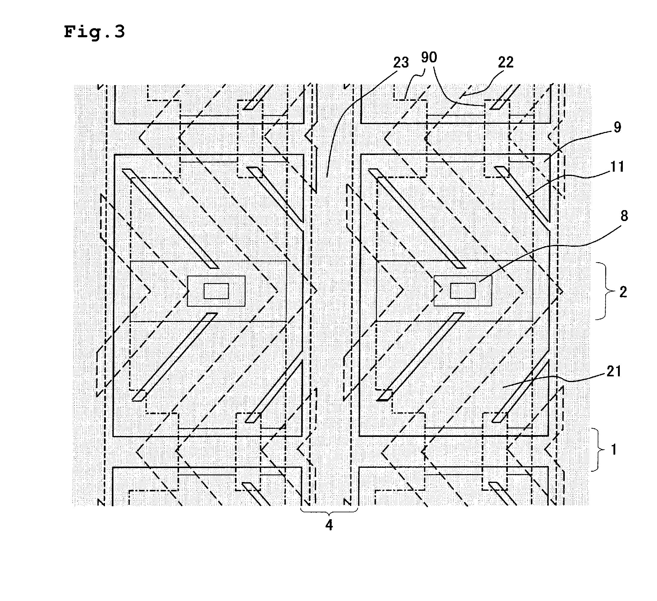
[0079] FIGS. 3 to 6 are plan views showing schematically a part of each of liquid crystal panels according to embodiments 2 to 5 of the present invention.

[0080] In the embodiment 1, although the slits 23 are located only at the site opposed to the gate wiring 1, slits 23 are located at the site opposed to a source wiring 4 as shown in FIG. 3 in the embodiment 2. Moreover, slits 23 are located at the site opposed to a wiring 2 for storage capacitor as shown in FIG. 4 in the embodiment 3. Furthermore, slits 23 are located at the site opposed to a gate wiring 1, a source wiring 4, and a wiring 2 for storage capacitor as shown in FIG. 5 in the embodiment 4. In addition, a color filter substrate 20 has a structure containing no BM as shown in FIG. 6 in the embodiment 5. Thus, it becomes possible to increase a panel aperture ratio, and there is no overlapped portion between the BM 90 and a colored layer, so that a barrier becomes lower, whereby advantageous effects of extending easily a ...


PUM


Abstract

It is an object of the present invention to provide a substrate for liquid crystal display by means of which a generation of air bubbles in a liquid crystal layer after charging a liquid crystal can be prevented, and a liquid crystal display having a good display quality level can be obtained at a high yield, and to provide a liquid crystal display unit provided with such substrate for liquid crystal display. The present invention is directed to a substrate for liquid crystal display, comprising a projection for controlling alignments of liquid crystal molecules, wherein a slit is provided in the projection for controlling alignments of liquid crystal molecules.

Description

TECHNICAL FIELD [0001] The present invention relates to a substrate for liquid crystal display and a liquid crystal display unit, and more particularly to a substrate for liquid crystal display used suitably for a MVA (multi-domain Vertical Alignment) type liquid crystal display and a liquid crystal display unit provided therewith. BACKGROUND ART [0002] Since a liquid crystal display has advantages of compact, thin, a low consumption of electric power, and light-weight, it is widely used for a variety of electronics devices at present. Particularly, an active matrix type liquid crystal display containing switching devices is widely adopted for business machines such as a personal computer, audio-video equipment such as TV, cellular phone and the like. In such liquid crystal displays, improvements in quality levels such as growing in size, high-definition, increase in a ratio of pixel effective area (high aperture ratio), wide visual field, and increase in color purity develop rapidl...

Claims


Application Information

Patent Timeline
IPC IPC(8): G02F1/1333G02F1/1341G02F1/1337
CPCG02F1/133707
Inventor TSUJI, MASAYUKITSUBATA, TOSHIHIDEHISADA, YUHKO
Owner SHARP KK
Why Eureka
Try Eureka