Color filter substrate

a color filter and substrate technology, applied in the field of color filter substrates, can solve the problems of high percentage of the overall fabrication cost of a color lcd, high cost of color filter, and low utilization efficiency of raw materials, and achieve the effect of improving the color saturation of a color liquid crystal display

Inactive Publication Date: 2007-09-20
WINTEK CORP
View PDF6 Cites 21 Cited by
  • Summary
  • Abstract
  • Description
  • Claims
  • Application Information

AI Technical Summary

Benefits of technology

[0007]Hence, an object of the invention is to provide a color filter substrate capable of transmitting high-resolution spectra of red, green, and blue light to improve the color saturation of a color liquid crystal display.

Problems solved by technology

Further, the color filter often takes up a high percentage of the overall fabrication cost of a color LCD. FIG. 1 shows a schematic diagram illustrating a conventional color filter substrate 100.
However, such fabrication method obviously has the following disadvantages.
First, with regard to the fabrication process, its spin coating process through which the dyeing photosensitive material is coated on the glass substrate results in low utilization efficiency of raw materials and thus increases the fabrication cost.
Further, as to the color performance, the red, green or blue light filtered out by the color filter substrate fabricated by the pigment-dispersed method has low spectrum resolution to result in an unsatisfactory color saturation of a color LCD.

Method used


Image

  • Color filter substrate
  • Color filter substrate
  • Color filter substrate

Examples


first embodiment

[0022]

TABLE 1LaminateMaterialThicknessReflective layersAg40 nmSpacer layer corresponding to red pixel portionSiO2190 nm Spacer layer corresponding to green pixel portionSiO2139 nm Spacer layer corresponding to blue pixel portionSiO292 nmInterference layerSi42 nm

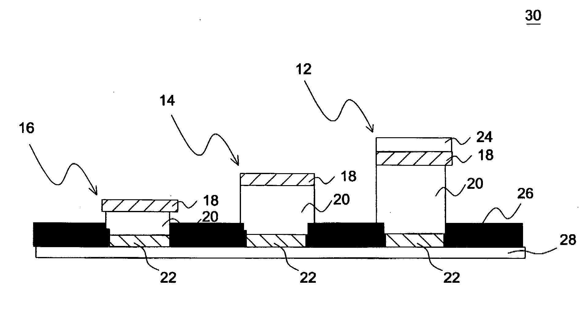
[0023]In this embodiment, the first and second reflective layers 18 and 22 are both made of silver (Ag) and have a thickness of 40 nm. The spacer layer 20 is made of silicon dioxide (SiO2) having a low refractive index.

[0024]FIGS. 4A-4D show the transmittance of a particular color versus the wavelength of light according to the selection listed in table 1. Referring to FIGS. 4A and 4B, it can be seen the blue pixel portion 16 and the green pixel portion 14 may output pure blue light and green light, respectively, under the selection of the spacer layer thickness listed in table 1. However, referring to FIG. 4C, as the thickness of the spacer layer 20 corresponding to the red pixel portion 12 is selected as 190 nm, an undesire...

second embodiment

[0026]

TABLE 2LaminateMaterialThicknessReflective layersAg40 nmSpacer layer corresponding to red pixel portionTiO299 nmSpacer layer corresponding to green pixel portionTiO268 nmSpacer layer corresponding to blue pixel portionTiO240 nmInterference layerSi42 nm

[0027]In this embodiment, the first and second reflective layers 18 and 22 are both made of silver (Ag) and have a thickness of 40 nm. The spacer layer 20 is made of titanium dioxide (TiO2) having a high refractive index.

[0028]FIGS. 6A-6D show the transmittance of a particular color versus the wavelength of light according to the selection listed in table 2. Referring to FIGS. 6A and 6B, it can be seen the blue pixel portion 16 and the green pixel portion 14 may output pure blue light and green light, respectively, under the selection of the spacer layer thickness listed in table 2. However, referring to FIG. 6C, as the thickness of the spacer layer 20 corresponding to the red pixel portion 12 is selected as 99 nm, an undesired p...

third embodiment

[0031]

TABLE 3LaminateMaterialThicknessReflective layersAg40nmSpacer layer corresponding to red pixel portionSiO2180.5nmSpacer layer corresponding to green pixel portionSiO2139nmSpacer layer corresponding to blue pixel portionSiO292nm

[0032]In this embodiment, the first and second reflective layers 18 and 22 are both made of silver (Ag) and have a thickness of 40 nm. The spacer layer 20 is made of silicon dioxide (SiO2) having a low refractive index. FIG. 7 shows the spectral characteristics of the output red light from the red pixel portion 12 when the thickness of the spacer layer 20 corresponding to the red pixel portion 12 is selected as 180.5 nm. As shown in FIG. 7, though an undesired peak also emerges at a wavelength of about 380 nm-400 nm of the output spectrum, it is comparatively small when compared with the undesired peaks shown in the first and second embodiments. From this embodiment, the chromaticity coordinate in a CIE 1931 chromaticity diagram (X,Y)=(0.529, 0.264), and...


PUM


Abstract

A color filter substrate includes a transparent substrate, a first and second reflective layers, a spacer layer, and an interference layer. The spacer layer is interposed between the two reflective layers and includes a plurality of first, second and third regions that are distinguished from one another according to their respective thicknesses, where the first, second and third regions overlap red, green and blue pixel portions, respectively. An interference layer is formed on the second reflective layer at positions overlapping the red pixel portions.

Description

BACKGROUND OF THE INVENTION[0001](a) Field of the Invention[0002]The invention relates to a color filter substrate, and more particularly to a color filter substrate using interference filters.[0003](b) Description of the Related Art[0004]The color filter is a critical component for a color liquid crystal display (color LCD) since the former certainly determines the color performance of the latter. Further, the color filter often takes up a high percentage of the overall fabrication cost of a color LCD. FIG. 1 shows a schematic diagram illustrating a conventional color filter substrate 100. Referring to FIG. 1, a black matrix 110 is spread on a glass substrate 102 and defines a plurality of opening regions in which red, green and blue color filters 104, 106 and 108 are formed. The black matrix 110 is used to improve the display quality by blocking the stray light passing through the gap between the pixel electrodes (not shown) that correspond to different color filters. Also, a tran...

Claims


Application Information

Patent Timeline
Patent Type & Authority Applications(United States)
IPC IPC(8): G02B5/22
CPCG02B5/28G02B5/201
Inventor CHEN, CHIEN-CHUNGHWANG, CHIN-PEI
Owner WINTEK CORP
Why Eureka
Try Eureka