Laminated ceramic capacitor

a laminated ceramic capacitor and ceramic capacitor technology, applied in the field of multi-terminal laminated ceramic capacitors, can solve the problems of increasing the risk of short-circuit failure between adjacent terminal electrodes, reducing the electrode width of terminal electrodes, and reducing the manufacturing yield and reliability. the effect of reliability, manufacturing yield and productivity improvemen

Active Publication Date: 2007-09-20
TDK CORPARATION
View PDF6 Cites 9 Cited by
  • Summary
  • Abstract
  • Description
  • Claims
  • Application Information

AI Technical Summary

Benefits of technology

[0013]In addition to the above-described basic structure of a multi-terminal laminated ceramic capacitor, the present invention is characterized in that at least outermost ones of the terminal electrodes in the length direction are each provided with an intermediate portion and an end portion, the intermediate portion has a larger electrode width than the led-out portion, and the end portion has a smaller electrode width at an edge of the side face than the intermediate portion. In this configuration, since at least the outermost terminal electrodes have a smaller width at the end portion than at the intermediate portion, the terminal electrodes adjacent each other in the length direction ensures a sufficient distance between their end portions. This reduces the risk of occurrence of solder bridging between the adjacent end portions during soldering to a mounting substrate, thereby preventing short-circuit failure.
[0014]Moreover, the intermediate portion of the terminal electrode, which has a larger electrode width than the end portion and the led-out portion and may be a central bulge of a barrel-shape, enables further reduction of ESL in a miniaturized laminated ceramic capacitor, thereby improving the high-frequency characteristic of the capacitor.
[0015]Furthermore, the intermediate portion of the terminal electrode prevents undesirable exposure of the led-out portion, thereby improving the reliability, the manufacturing yield and the productivity of the laminated ceramic capacitor.

Problems solved by technology

Under normal conditions, however, the miniaturization of laminated ceramic capacitors necessarily reduces the electrode width of terminal electrodes, contrary to the demand for low ESL.
In addition, reducing the electrode width of terminal electrodes greatly increases the risk of undesirable exposure of internal electrodes, causing decrease in the manufacturing yield and the reliability.
This greatly increases the risk of short-circuit failure between adjacent terminal electrodes, for example, due to occurrence of solder bridging during soldering to a mounting substrate.

Method used


Image

  • Laminated ceramic capacitor
  • Laminated ceramic capacitor
  • Laminated ceramic capacitor

Examples


Embodiment Construction

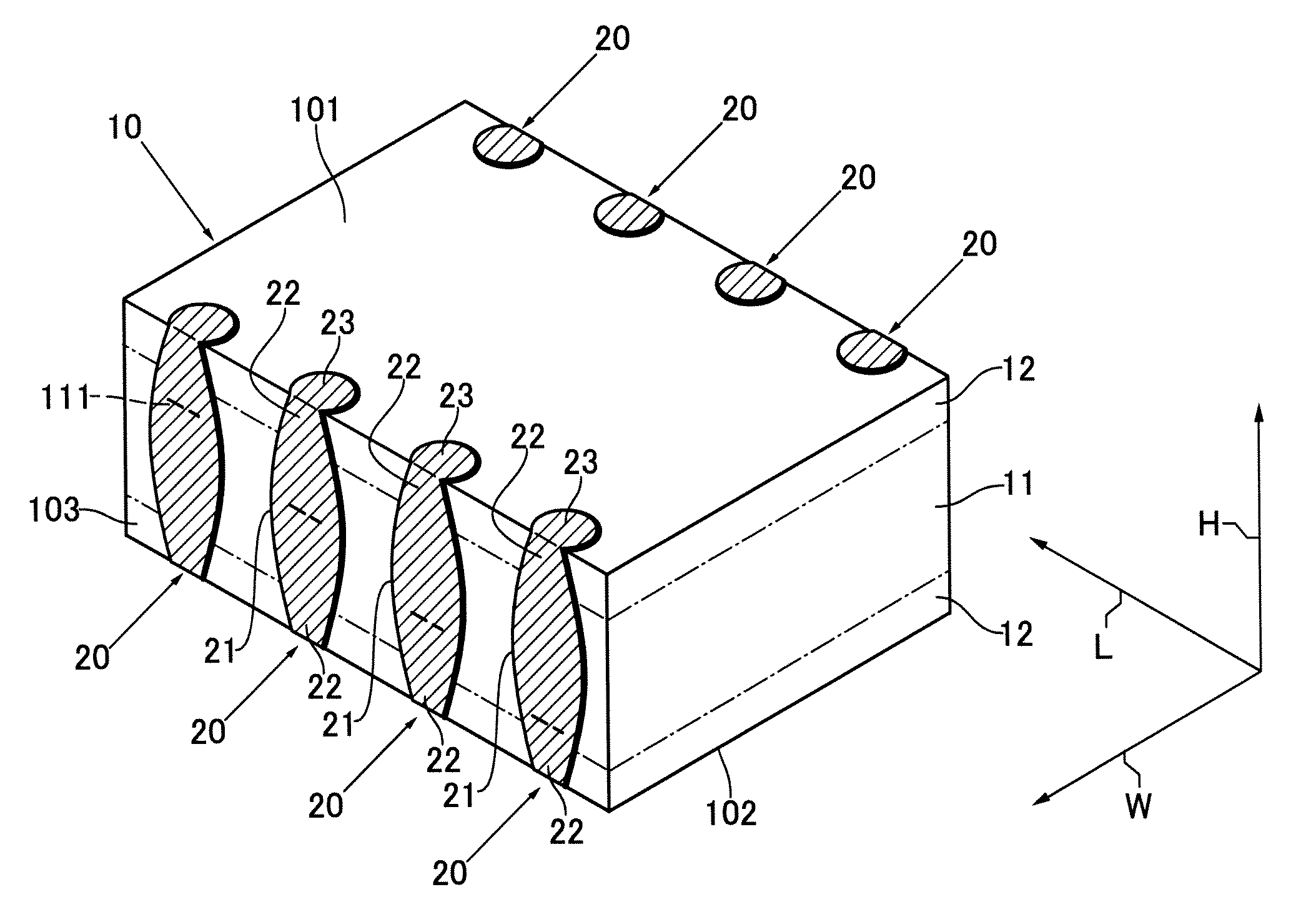
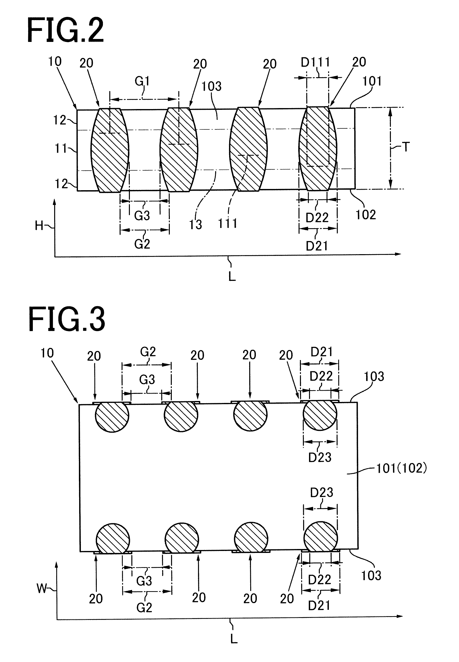
[0031]In a laminated ceramic capacitor shown in FIGS. 1 to 4, a body 10 is a hexahedron having one face 101 and another face 102 opposite from the face 101 in a height direction H. The body 10 has a height T and is composed inner and outer layer portions 11 and 12.

[0032]The inner layer portion 11 is formed by stacking a predetermined number of dielectric layers 112 in the height direction H, wherein the dielectric layer 112 is mainly composed of a ceramic dielectric material and an internal electrode 110 mainly composed of a conductive metallic material is patterned on one surface of the dielectric layer 112. In order to realize low ESL, it is preferred that the polarity is different between adjacent ones of the internal electrodes 110 in the height direction H.

[0033]Each internal electrode 110 has at least one led-out portion 111 that is used as a so-called “extraction electrode”. The led-out portion 111 is led out to at least one of two opposite side faces 103 of the body 10 in a ...


PUM

PropertyMeasurementUnit
heightaaaaaaaaaa
heightaaaaaaaaaa
lengthaaaaaaaaaa

Abstract

A laminated ceramic capacitor includes a body having an inner layer portion and an outer layer portion and a plurality of terminal electrodes spaced apart from each other in a length direction of the body. The inner layer portion has a plurality of internal electrodes stacked in a height direction of the body. The internal electrodes have led-out portions led out to a side face of the body. The outer layer portion is disposed on one of opposite faces of the inner layer portion in the height direction. Each terminal electrode extends along the height direction to cover corresponding one of the led-out portions and is provided with an intermediate portion and an end portion. The intermediate portion has a larger electrode width than the led-out portion. The end portion has a smaller electrode width at an edge of the side face than the intermediate portion.

Description

BACKGROUND OF THE INVENTION[0001]1. Field of the Invention[0002]The present invention relates to a multi-terminal laminated ceramic capacitor with low ESL.[0003]2. Description of the Related Art[0004]Such laminated ceramic capacitors have been required to have ESL reduced with increase in frequency of electronic devices on which the capacitors are to be mounted. As means for realizing low ESL, Japanese Unexamined Patent Application Publication No. 2000-208361 discloses increasing the electrode width of terminal electrodes.[0005]Recently, furthermore, the market demand for miniaturization of electronic devices has been rapidly increasing, and further miniaturization of laminated ceramic capacitors to be mounted thereon is also demanded in accordance with the technical trend.[0006]Under normal conditions, however, the miniaturization of laminated ceramic capacitors necessarily reduces the electrode width of terminal electrodes, contrary to the demand for low ESL.[0007]In addition, red...

Claims


Application Information

Patent Timeline
Patent Type & Authority Applications(United States)
IPC IPC(8): H01G4/228
CPCH01G4/232H01G4/30H05K2201/10727H05K2201/09381H05K3/3442Y02P70/50H01G4/12
Inventor TOGASHI, MASAAKIOKUYAMA, HIROSHISUYAMA, SHINYA
Owner TDK CORPARATION
Why Eureka
Try Eureka