Heat dissipation device

a heat sink and heat dissipation technology, applied in semiconductor devices, cooling/ventilation/heating modifications, semiconductor/solid-state device details, etc., can solve the problems of heat sinks that cannot dissipate heat transferred from heat pipes quickly and efficiently, heat sinks that cannot be too large, etc., to achieve high heat dissipation capability and heat sinks that do not need to be reduced.

Inactive Publication Date: 2007-09-20
FU ZHUN PRECISION IND SHENZHEN +1
View PDF25 Cites 26 Cited by
  • Summary
  • Abstract
  • Description
  • Claims
  • Application Information

AI Technical Summary

Benefits of technology

[0005] A heat dissipation device comprises a heat conducting plate for contacting with an electronic component, a heat sink mounted on the heat conducting plate and a heat pipe. A groove is defined in the heat conducting plate. The heat pipe comprises an evaporating portion sandwiched between the heat conducting plate and the heat sink, and a condensing portion thermally connecting with the heat sink. The evaporating portion comprises a middle portion having a circular cross section and accommodated in the groove of the heat conducting plate, and a pair of end portions formed on opposite sides of the middle portion. The end portions each have a semi-circular configuration to accommodate other electronic components such as capacitors therebelow. Thus, a size of the heat sink does not need to be reduced, and a high heat dissipation capability of the heat sink can be maintained. Furthermore, a thickness of the heat conducting plate can be reduced to enable the middle portion of the evaporation portion to be located closer to the electronic component, whereby heat generated by the electronic component can quickly reach the evaporation portion of the heat pipe and the heat sink through the heat pipe.

Problems solved by technology

When a CPU operates at a high speed in a computer enclosure, its temperature usually increases enormously.
However, in some situations, the heat sink can not be too large, for example, other components such as electric capacitor are located around the electronic component to be cooled.
Therefore, the heat-exchanging area of the heat sink is small, and the heat sink can not dissipate the heat transferred from the heat pipes quickly and efficiently any longer.
The heat will be accumulated at the heat sink, which may result in that the temperature difference between the evaporating and condensing portions of the heat pipes getting lower, and the heat pipes can not quickly and efficiently remove the heat produced by the electronic component.
Therefore, when a higher component is located around the electronic component to be cooled, the conventional heat dissipation device can not keep the electronic component to be cooled in a normal temperature range, which affects the normal operation of the electronic component.

Method used


Image

  • Heat dissipation device
  • Heat dissipation device
  • Heat dissipation device

Examples


Embodiment Construction

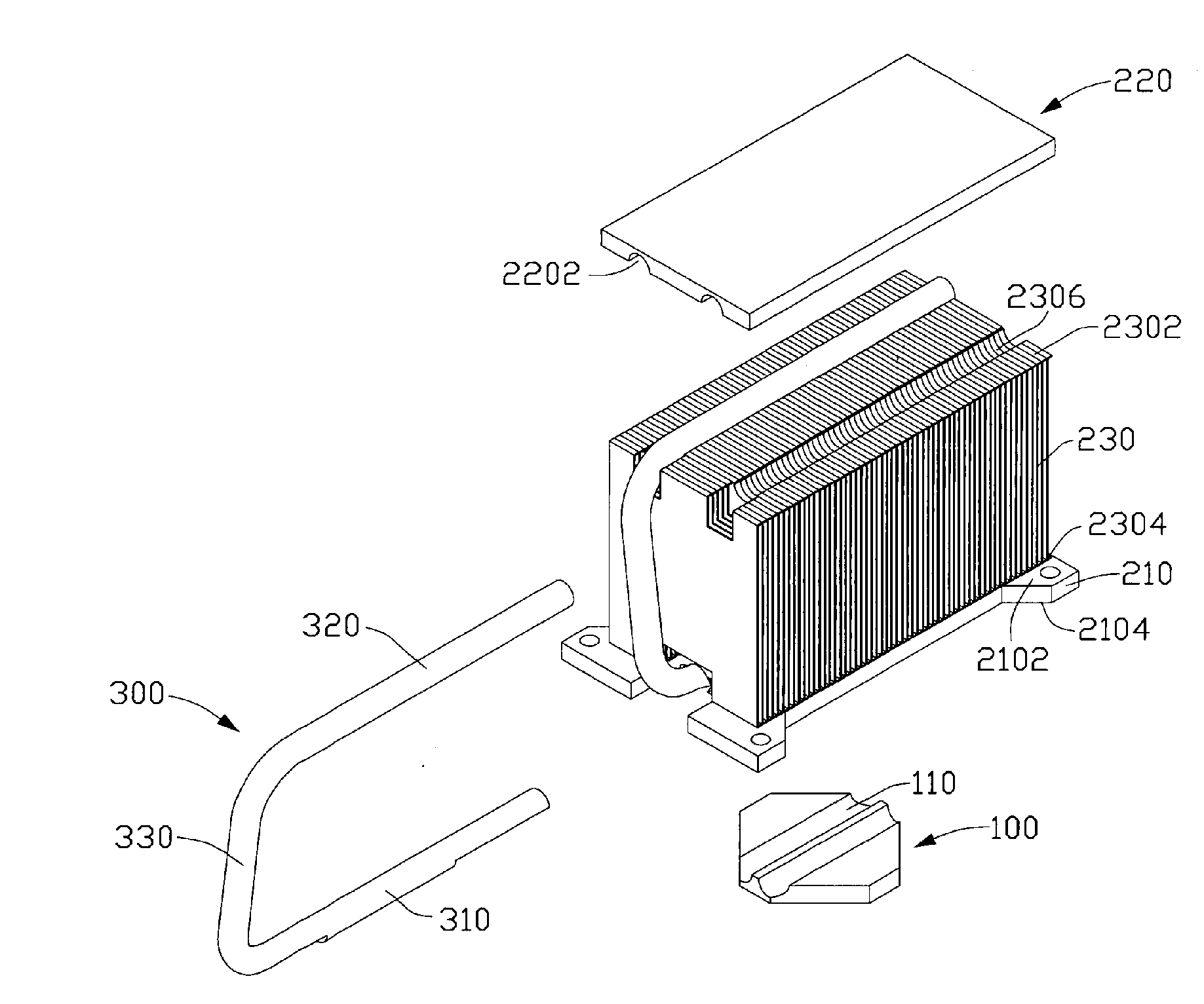
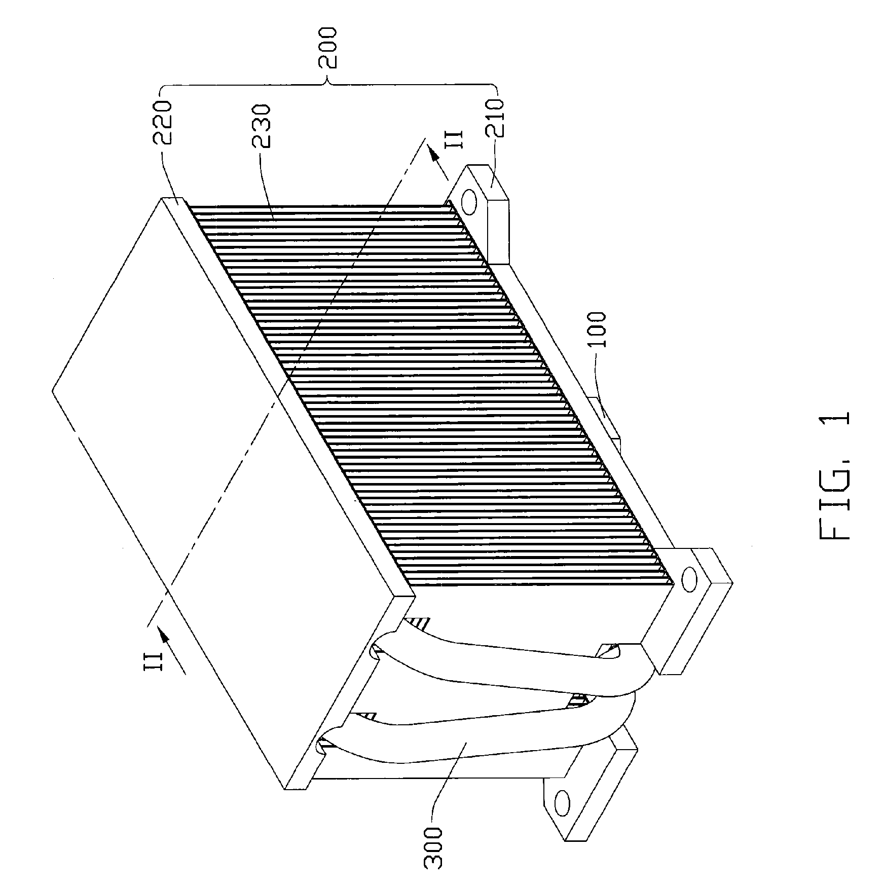
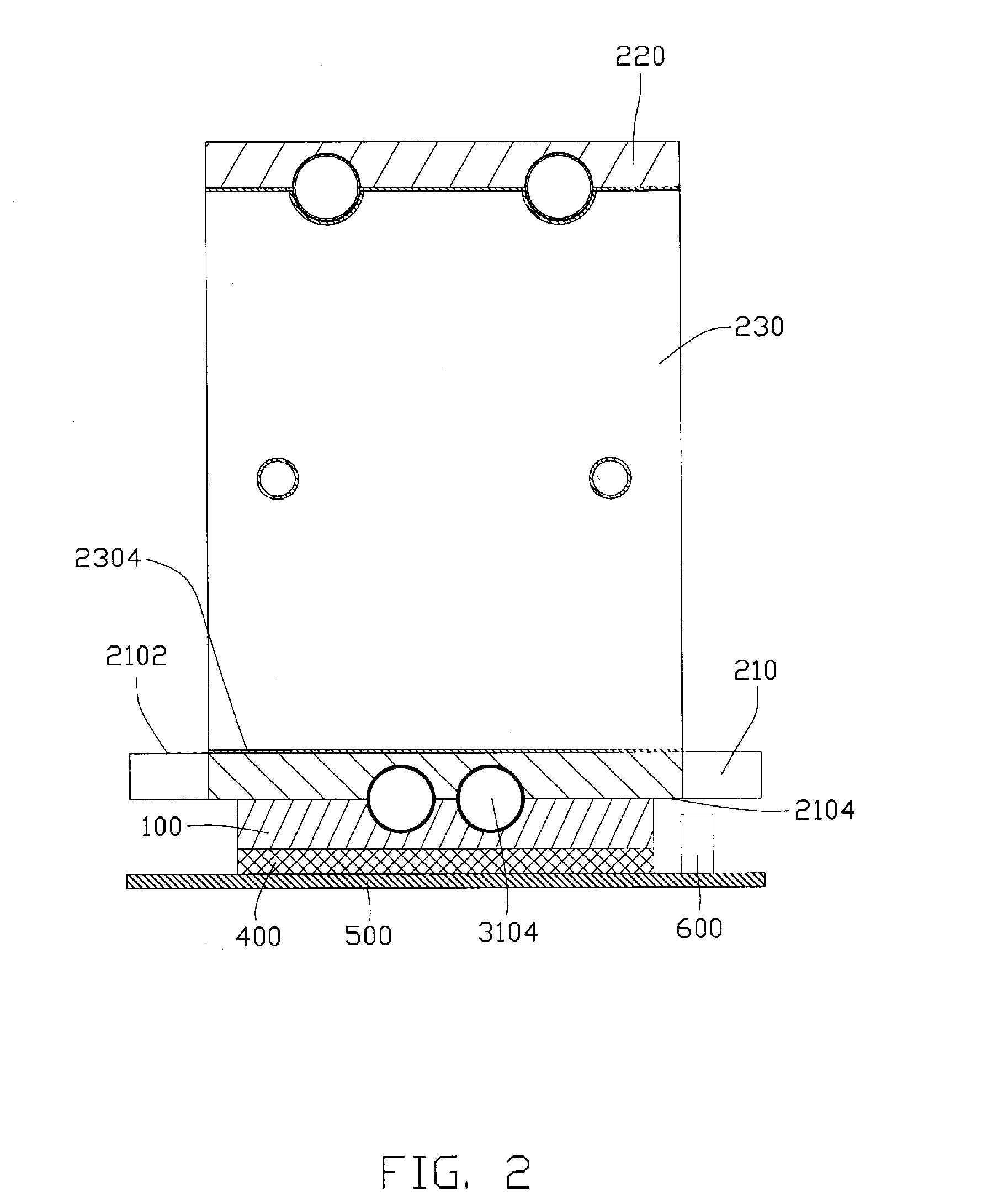
[0013] Referring to FIGS. 1-5, a heat dissipation device in accordance with a preferred embodiment of the invention comprises a heat conducting plate 100, a heat sink 200 mounted on the heat conducting plate 100 and two heat pipes 300 thermally connecting with the heat conducting plate 100 and the heat sink 200.

[0014] The heat conducting plate 100 is made of heat conductive material such as copper or aluminum, and is used for contacting with an electronic component 400 mounted on a printed circuit board 500 and absorbing heat therefrom. The heat conductive plate 100 comprises a pair of parallel grooves 110 defined in an upper portion thereof for receiving heat pipes 300 and conducting the heat to the heat pipes 300. The heat conducting plate 100 is also used for preventing the heat dissipation device of present invention from interfering with other component 600 mounted on the printed circuit board 500. The thickness of the heat conducting plate 100 is designed to keep the heat sin...


PUM


Abstract

A heat dissipation device includes a heat conducting plate (100) for contacting with an electronic component (400), a heat sink (200) mounted on the heat conducting plate and a heat pipe (300). The heat conducting plate comprises a groove (110) defined in. The heat pipe comprises an evaporating portion (310) sandwiched between the heat conducting plate and the heat sink, and a condensing portion (320) thermally connecting with the heat sink. The evaporating portion comprises a middle portion (3104) having a circular cross section and accommodated in the groove of the heat conducting plate, and a pair of end portions (3102) formed on opposite sides of the middle portion. The end portions have flat bottom surfaces.

Description

FIELD OF THE INVENTION [0001] The present invention relates to a heat dissipation device, and more particularly to a heat dissipation device including a heat sink and heat pipes for achieving a better heat dissipation efficiency. DESCRIPTION OF RELATED ART [0002] As computer technology continues to advance, electronic components such as the central processing units (CPUs) of computers are made to provide faster operational speeds and greater functional capabilities. When a CPU operates at a high speed in a computer enclosure, its temperature usually increases enormously. It is desirable to dissipate the generated heat of the CPU quickly. [0003] Conventionally, a heat dissipation device is used to dissipate heat generated by a CPU. A conventional heat dissipation device generally comprises a heat sink and heat pipes attached to the heat sink. The heat sink comprises a base for contacting with an electronic component mounted on a printed circuit board and a plurality of fins extending...

Claims


Application Information

Patent Timeline
Patent Type & Authority Applications(United States)
IPC IPC(8): H05K7/20
CPCH01L23/3672H01L23/427H01L2924/0002H01L2924/00
Inventor LAI, CHENG-TIENZHOU, ZHI-YONGLIU, YI-SAN
Owner FU ZHUN PRECISION IND SHENZHEN
Why Eureka
Try Eureka