Stent Graft Repair Device

US20070219620A1Active Publication Date: 2007-09-20COOK MEDICAL TECH LLC

Image

  • Stent Graft Repair Device
  • Stent Graft Repair Device
  • Stent Graft Repair Device

Examples


Embodiment Construction

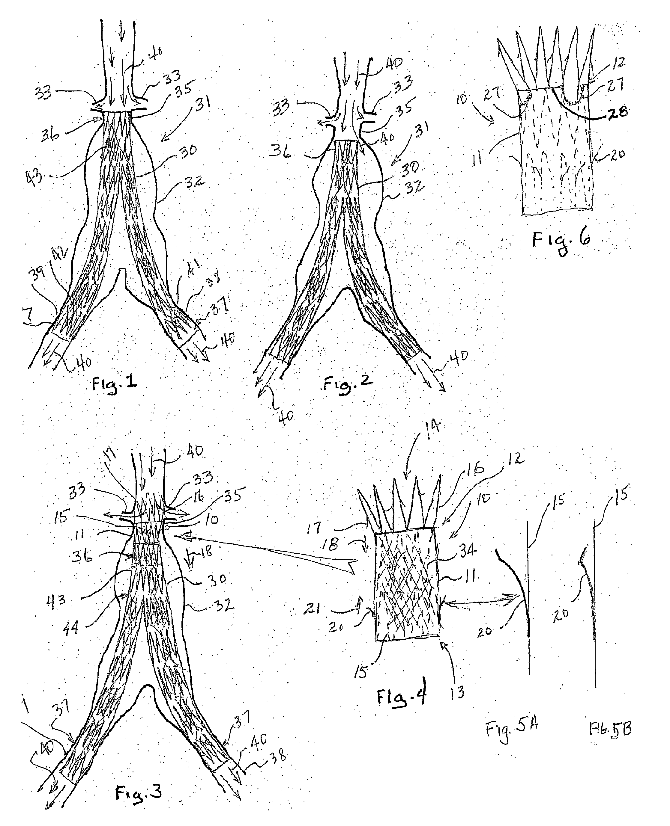
[0017] The stent graft repair device of this invention can be delivered by a simple commercially available sheath and dilator system (COOKĀ® Incorporated, Bloomington, Ind.) wherein the dilator portion has a recess or indentation to accommodate the compressed device. Delivery can be by percutaneous methods over a guide wire from either above (trans jugular) or from below via the femoral arteries. The low profile, flexible nature of this delivery system, which is made possible in large part by barb 20 as shown in FIGS. 5A and 5B, is ideal for passage through a previously placed stent graft. The lack of ledges or joints as would be the case with a hard capsule, minimizes the chance that the delivery system will catch or tangle with the stents or graft material of the previously placed stent graft. This device could also be delivered in a delivery system similar to the H&LB One Shot delivery system as used for the ZENITHĀ® AAA stent graft as commercially available from Cook Incorporated,...


PUM


Abstract

A repair device (10) for affixing a migrating stent graft (30) to the interior surface of a vessel wall (31). The repair device includes tubular graft (11) with a bare or uncovered stent (16) affixed to the proximal end (12). The bare stent includes a plurality of distally pointed barbs (17) for securing the repair device to a vessel wall. A second stent (15) is positioned in the passage (14) of the tubular graft to expand the graft against the interior surface of the migrating stent graft (30). Proximally pointing barbs (20) are affixed to the struts of the second stent and extend through the graft material for securing the repair device to the migrating stent graft. Biological glue (22) and other sealing material (23) can be applied to the tubular graft and / or stents for sealing the repair device against the vessel wall and / or the interior of the migrating stent graft.

Description

TECHNICAL FIELD [0001] This invention relates to medical devices and, in particular, to stent grafts. More specifically the invention is directed to a repair device for correcting leakage at the proximal (inflow) end of a stent graft due to migration or changes in the aneurysm that result in blood pressure being restored to the aneurysm sack, which could cause it to rupture. BACKGROUND OF THE INVENTION [0002] In many cases of abdominal aortic aneurysm (AAA), the diseased or weakened portion of the artery is near or up to the origins of the renal arteries. In these cases, it is difficult to get firm anchoring of the proximal end of an AAA stent graft. If the top stent of the stent graft cannot anchor to several millimeters of healthy tissue, there is a likelihood that there will be leakage around the top of the stent graft and / or migration of the stent graft out of the anchor area or ā€œneckā€, resulting in even more leakage and the failure of the stent graft to protect the aneurysm fro...

Claims


Application Information

Patent Timeline
20 Sep 2007
Publication
US20070219620A1
IPC
A61F2/06; A61F2/82
CPC
A61F2/07; A61F2220/0075; A61F2002/065; A61F2002/067; A61F2002/075; A61F2002/826; A61F2002/8483; A61F2002/8486
Inventors
EELLS, SCOT E.; OSBORNE, THOMASA