Hydraulic vehicle stabilizer system with two-stage bi-rotational hydraulic pump system

Active Publication Date: 2007-09-27
PARKER INTANGIBLES LLC
View PDF19 Cites 6 Cited by
  • Summary
  • Abstract
  • Description
  • Claims
  • Application Information

AI Technical Summary

Benefits of technology

[0008] The present invention provides a stabilizer system and method that can provide high speed, relatively low force extension and retraction of a stabilizer leg during a first portion of a stroke, and low speed, relatively high force

Problems solved by technology

Accordingly, as the load capacity increases the stabilizer system takes longer to deploy thereby making the system less convenient to use.
However, using a more powerful pump usually means increased costs and may also

Method used


Image

  • Hydraulic vehicle stabilizer system with two-stage bi-rotational hydraulic pump system
  • Hydraulic vehicle stabilizer system with two-stage bi-rotational hydraulic pump system

Examples


Example

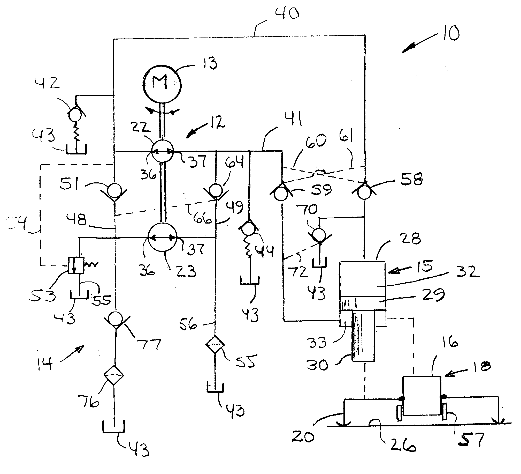
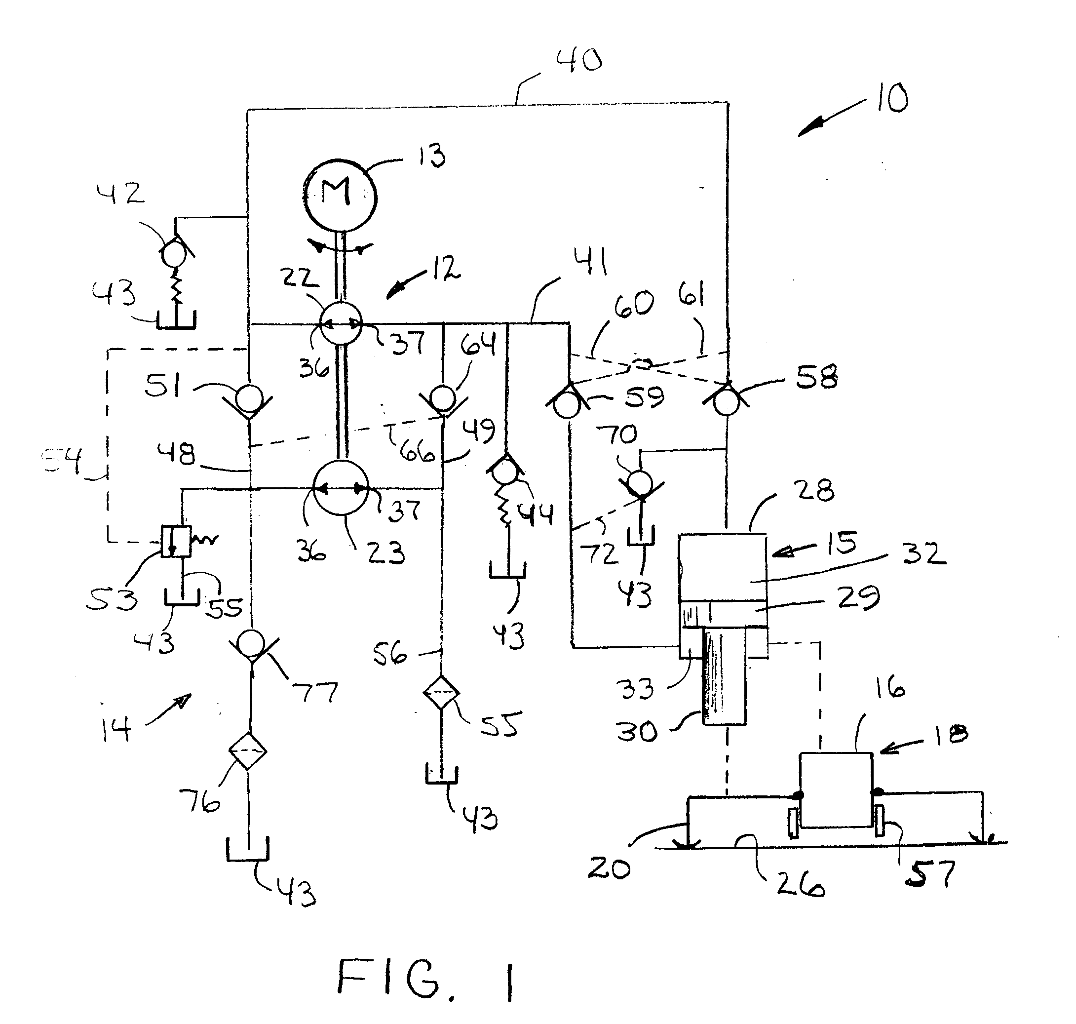
[0034] Referring now to the drawing, an exemplary hydraulic system according to the invention is generally indicated at 10. The system 10 generally comprises a pump assembly 12 that can be driven by a prime mover such as a reversible motor 13, in particular a DC motor, in both directions, and hydraulic circuitry 14 for connecting the pump assembly to a hydraulic actuator 15. As illustrated, the actuator 15 can be mounted to a body 16 of a vehicle 18 and connected to a stabilizer leg 20 for lowering and raising the leg upon extension and retraction of the actuator. The vehicle typically will be equipped with one or more additional stabilizer legs each serviced by a respective pump assembly (not shown) and associated hydraulic circuitry (not shown) that may be the same as that herein described. The stabilizer legs can be lowered to raise the vehicle body and support the vehicle body independently of its suspension.

[0035] As will be appreciated by those skilled in the art, a more powe...


PUM


Abstract

A stabilizer system and method that can provide high speed, relatively low force extension and retraction of a stabilizer leg during a first portion of a stroke, and low speed, relatively high force extension and retraction during a second portion of the stroke. Accordingly, the stabilizer system and method takes less time to deploy than conventional stabilizer systems but without sacrificing performance.

Description

RELATED APPLICATION [0001] This application claims the benefit of U.S. Provisional Application No. 60 / 785,144 filed Mar. 23, 2006, which is hereby incorporated herein by reference.FIELD OF THE INVENTION [0002] The present invention relates generally to hydraulic vehicle stabilizer systems and, more particularly, to such a system using a two-stage bi-rotational hydraulic pump. The invention also has more general applicability to bi-directional actuator systems using a two-stage bi-rotational hydraulic pump. BACKGROUND OF THE INVENTION [0003] A trend in the construction industry has been to utilize smaller, more versatile machinery on the job-site. For example, mini-excavators and skid-steer loaders are often used to perform a variety of tasks. In many cases, a skid-steer loader or mini-excavator is equipped with an attachment for performing a particular task. Such attachments are typically powered by an auxiliary hydraulic circuit on the skid-steer loader or mini-excavator. Numerous ...

Claims


Application Information

Patent Timeline
IPC IPC(8): F16D31/02
CPCE02F9/085F15B11/17F15B2211/20538F15B2211/20561F15B2211/7053F15B2211/20592F15B2211/265F15B2211/6052F15B2211/615F15B2211/20584
Inventor KUBINSKI, PAUL T.
Owner PARKER INTANGIBLES LLC
Why Eureka
Try Eureka