High efficiency electronic ballast for metal halide lamp

a technology of electronic ballast and metal halide lamps, applied in the direction of electric variable regulation, process and machine control, instruments, etc., can solve the problems of low ballast efficiency, high heat generation, and high transfer loss of isolation transformers, and achieve low impedance, not reducing ballast efficiency, and high impedance

Inactive Publication Date: 2007-09-27
FUJIAN JUAN KUANG YAMING ELECTRIC
View PDF2 Cites 6 Cited by
  • Summary
  • Abstract
  • Description
  • Claims
  • Application Information

AI Technical Summary

Benefits of technology

[0013] It is an object of the invention to be able to find a stable operation frequency area which has a lower probability to cause the acoustic resonance.
[0022] The other object of the invention is to be able to make the ballast operate stable from starting to normal operation. The object was achieved by a MCU timer-controller with a modulation control algorithm. The algorithm will control the modulation depending on the status of the operation of the ballast. When the ballast finds the lamp in starting phase, it will cut off the frequency modulation until the lamp is operating in full power status. Compared with the U.S. Pat. No. 6,696,800, it needs a circuit to detect the lamp voltage. It costs more and is more complex.
[0024] Another object of the invention is to be able to short the output leads to ground without damage the ballast. It is achieved by using two DC block capacitors to isolate the lamp without an isolation transformer. The capacitor has very low impedance at operation frequency. Therefore, it will not reduce the efficiency of the ballast. The capacitor has very high impedance at low frequency (line frequency). Therefore, when the output leads short to ground (low frequency), the ballast will not be damaged.
[0025] It is an object of the invention to provide a controlled secondary power supply using a very simple circuit. This is done by adding an additional winding to the PFC boost inductor, diodes, capacitors, and voltage regulator complete the secondary power supply. This power supply provides power to the half-bridge converter. When the PFC stops, the secondary power supply turns off causing the half-bridge converter to shut off as well. This is a more efficient method of control than on traditional electronic ballast which uses a complicated status detection logic circuit. This design is simpler and lower the cost.

Problems solved by technology

The drawback is that the isolation transformer has very high transfer loss and generates a lot of heat.
Therefore, the efficiency of the ballast is lower and reliability of the ballast is lower as well.
It will cause damage to the transistor.
The circuit is quite complicated.
The overall circuit is still quite complicated.
However, it will not work for all kind of lamps.
The EMI noise is increased as well.
Therefore, the ballast cost is high and the ballast lose is high as well.
With deep frequency, modulation will cause the metal halide lamp flicker in starting phase.
It detects MH lamp voltage to determine the modulation deep rate, it also can avoid the starting phase flicker of the MH lamp, but the drawback is the detect lamp voltage circuit cost more and is complexity.

Method used


Image

  • High efficiency electronic ballast for metal halide lamp
  • High efficiency electronic ballast for metal halide lamp
  • High efficiency electronic ballast for metal halide lamp

Examples


Embodiment Construction

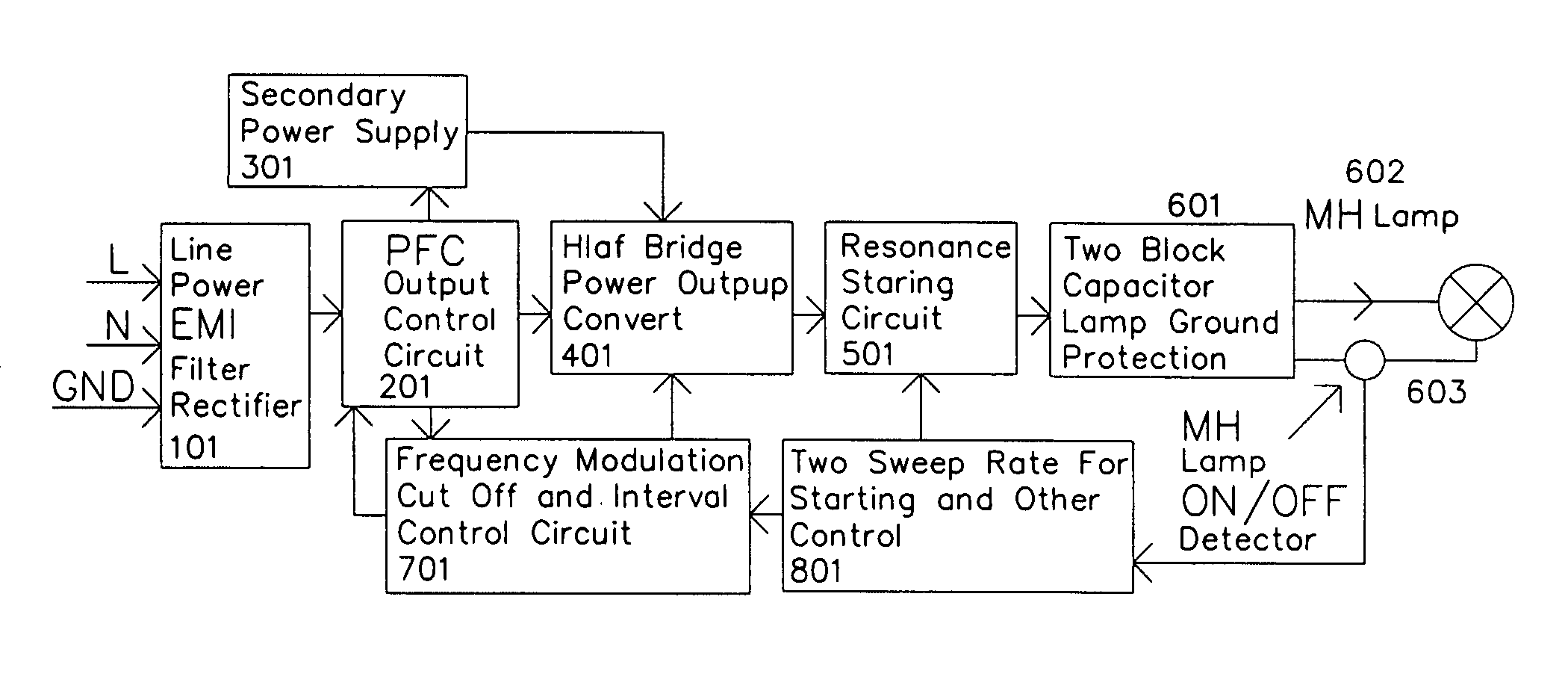
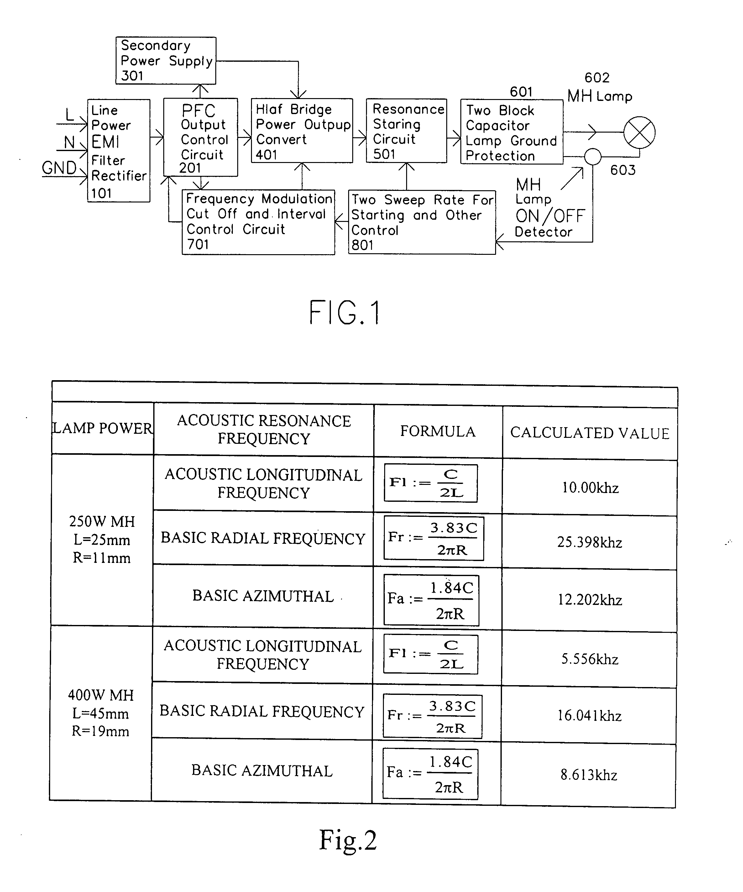
[0037] A high efficiency electronic ballast for large power (250 W, 400 W) metal halide lamp includes an EMI filter circuit. (101.), a. power factor correction circuit (201), a secondary power supply (301), a low frequency modulation and MCU control circuit (701), a half bridge power converter (401), a two sweep rate resonant starting circuit (801), and a lamp on / off detector (603). The half bridge power converter has the two DC block output capacitor (601) to protect the converter when the lamp output terminal is shorted to ground.

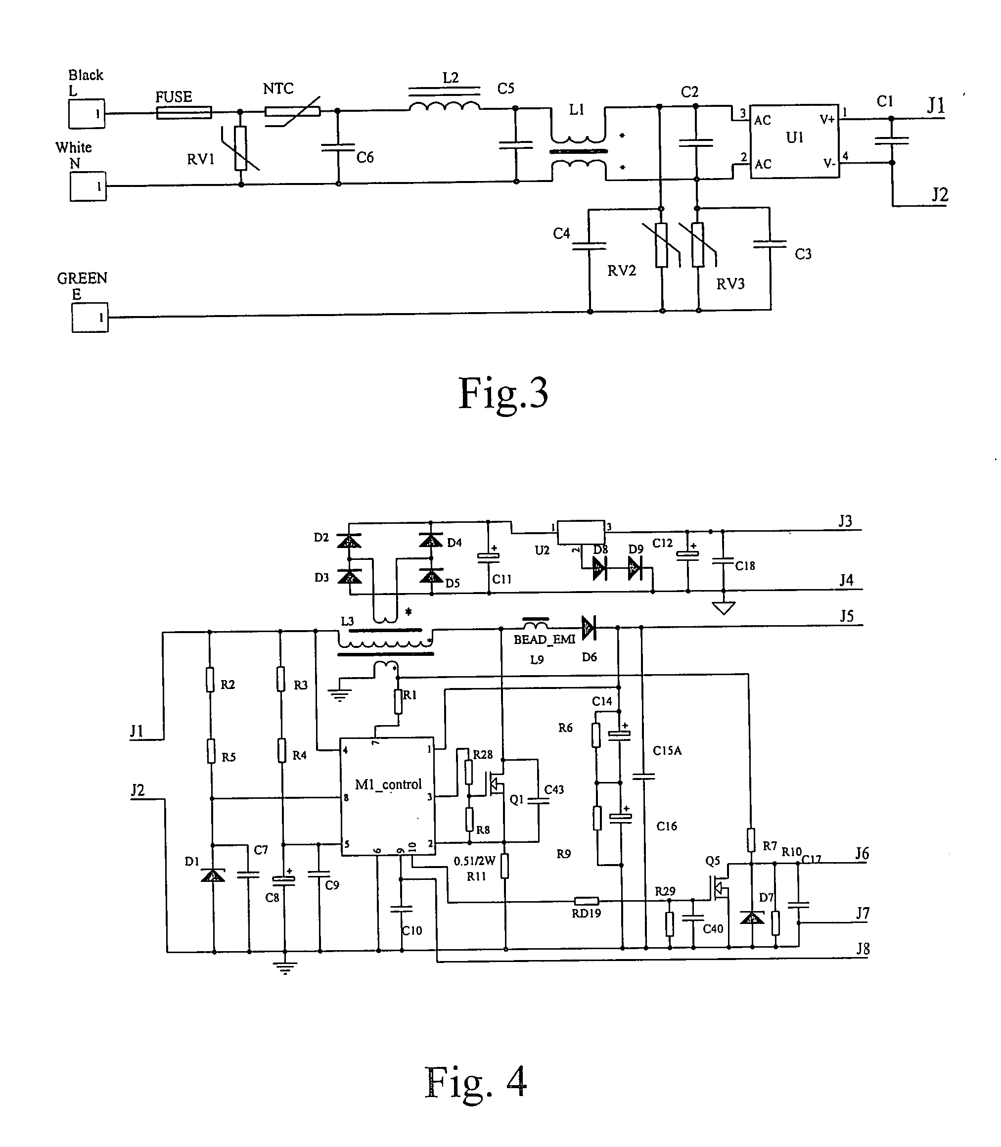
[0038] In FIG. 1 the block (101) contains the input stage of a high efficiency electronic ballast for a metal halide lamp. The detailed example is shown in FIG. 3.

[0039] L, N, E are line, neutral, and earth, respectively, for the power line input. Terminal J1, J2 connected to power factor correction part and a second control power supply. They consist of a fuse, varistor (RV1, RV2, RV3) for lighting protection, NTC for suppressive inrush line current, d...


PUM


Abstract

A high efficiency electronic ballast for large power metal halide lamp includes a power input circuit, a power factor correction circuit, a secondary power supply, a control circuit, a half bridge power converter, a resonant starting circuit, and lamp current on / off detector. The half bridge power converter has two DC block output capacitor to protect the converter when the output is shorted to ground. The operation frequency of the converter is chosen in the weak area of the acoustic resonant to avoid the acoustic resonant in the lamp. The control circuit adds a method for deep frequency and amplitude modulation and delay control function to the converter. For fine sweep pass through the output resonance point for igniting high voltage, two sweep rate control circuits are added. The metal halide lamp can be operated with very stable from starting to normal operation with high electronic ballast system efficiency.

Description

CROSS REFERENCE OF RELATED APPLICATIONS [0001] This is a non-provisional application of a provisional application having an application No. 60 / 780,150 and a filing date of Mar. 07, 2006. BACKGROUND OF PRESENT INVENTION [0002] 1. Field of Invention [0003] The present invention relates to high efficiency electronic ballast for a large power (250 W, 400 W) metal halide lamp. More specifically, the invention related to a high efficiency electronic ballast for a metal halide lamp that operates at 100 k-220 kHz (for 400 W lamp) or 180 k-300 kHz (for 250 W lamp) with different modulation at different operation period Consequence, the electronic ballast can operate the large power (250 W, 400 W) metal halide lamp very stable from starting to normal operation without the disadvantage of the complicated of low frequency with the high loss and low efficiency compare with the higher frequency operation. The efficiency of the electronic ballast is typically greater than 95%. The invention relate...

Claims


Application Information

Patent Timeline
Patent Type & Authority Applications(United States)
IPC IPC(8): H05B41/36
CPCY02B20/208H05B41/2925Y02B20/00Y10S315/02
Inventor CHEN, HEPINGCHEN, MINKONG, QINZHANG, WENXIONG
Owner FUJIAN JUAN KUANG YAMING ELECTRIC
Why Eureka
Try Eureka