Variable gain amplifier and communication apparatus

a gain amplifier and variable gain technology, applied in the field of variable gain amplifiers, can solve the problem of no transistor operating with a very small operation current, and achieve the effect of suppressing linearity deterioration and wide range of gain variation

Inactive Publication Date: 2007-09-27
SHARP KK
View PDF7 Cites 28 Cited by
  • Summary
  • Abstract
  • Description
  • Claims
  • Application Information

AI Technical Summary

Benefits of technology

[0010]An object of the present invention is to provide a variable gain amplifier capable of obtaining a wide rang

Problems solved by technology

In addition, there is no transistor that op

Method used


Image

  • Variable gain amplifier and communication apparatus
  • Variable gain amplifier and communication apparatus
  • Variable gain amplifier and communication apparatus

Examples


Embodiment Construction

[0046]An embodiment of the present invention will be described. The embodiment is an example in which the present invention is applied to a low noise amplifier provided in a communication apparatus such as a stationary television receiver or a cellular phone.

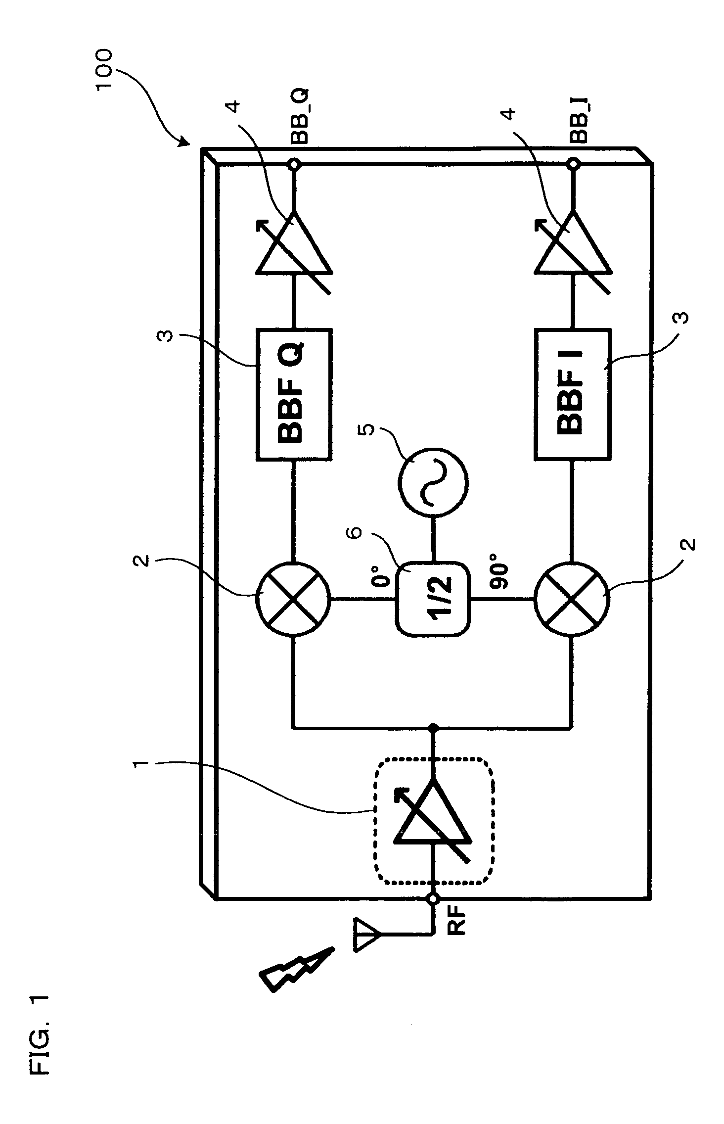
[0047]FIG. 1 shows a general construction of a receiving circuit of a communication apparatus 100 according to the embodiment. The communication apparatus 100 of the embodiment includes therein a low noise amplifier (LNA) 1; mixers 2, each of which serves as a frequency converter; base band filters (BBFs) 4; BB variable gain amplifiers (BBVGAs) 4; and so on. The circuit from the LNA 1 through the mixers 2 and the BBFs 3 to the BBVGAs 4 is formed into an LSI on a single chip.

[0048]An RF signal of, for example, 474-864 MHz, received through an antenna, is amplified by the LNA 1, and then input to two mixers 2. The mixers 2 are input with local (LO) signals different in phase by 90 degrees, from a voltage controlled oscillator (VCO...


PUM


Abstract

A variable gain amplifier is provided that can obtain a wide range of gain variation and suppress the deterioration of linearity when switching between amplifying transistors. The variable gain amplifier includes a plurality of cascode amplifiers each including an amplifying transistor and a plurality of cascode transistors connected in a cascode arrangement to an output terminal of the amplifying transistor. The plurality of cascode amplifiers are connected through attenuators. The variable gain amplifier further includes a first controller that controls ON/OFF operations of the plurality of cascode transistors included in each cascode amplifier; and a second controller that controls ON/OFF operations of a plurality of amplifying transistors, only one of which is included in each of the plurality of cascode amplifiers, such that only selected one of the plurality of amplifying transistors is turned on.

Description

BACKGROUND OF THE INVENTION[0001]1. Field of the Invention[0002]The present invention relates to a variable gain amplifier whose gain is variable, and also to a communication apparatus including therein the amplifier.[0003]2. Description of Related Art[0004]A conventional communication apparatus for, for example, transmitting / receiving television broadcasting signals, includes therein a variable gain amplifier constructed so that its gain is variable. For example, a receiving circuit of the communication apparatus includes therein a low noise amplifier (LNA), as a variable gain amplifier, for amplifying radio frequency (RF) signals received through an antenna.[0005]When a target wave received is weak, the gain of the LNA is set to a large value so that the influence of noise to be generated in each circuit can be suppressed as much as possible and thereby high sensitivity of reception can be obtained. Contrastingly, when an interfering wave exists or the target wave is high in inten...

Claims


Application Information

Patent Timeline
IPC IPC(8): H03F3/45H03F1/22
CPCH01L27/0207H01L29/41758H01L29/4238H03F1/223H03F1/26H03G1/0088H03F2200/294H03F2200/372H03F2203/7236H03G1/0029H03F3/72
Inventor KOUTANI, MASATOIIZUKA, KUNIHIKOKAWAMURA, HIROSHI
Owner SHARP KK
Why Eureka
Try Eureka