Millimeter wave image processor and millimeter wave image processing method

Inactive Publication Date: 2007-09-27
NEC CORP
View PDF8 Cites 14 Cited by
  • Summary
  • Abstract
  • Description
  • Claims
  • Application Information

AI Technical Summary

Benefits of technology

[0029]As described above, according to the present invention, in a passive method in which a target is monitored by receiving a millimeter wave of 94 GHz for example, it is possible to acquire clear image data irrespective of the target distance, from very near to far distance, to the two dimension antennas deployed vertically and horizontally. Further, even if the antennas or receiving systems are subject to environmental temperature changes and mechanical distortion and the received signal

Problems solved by technology

The art shown in Patent Document 1 was developed considering the fact that image scanning within a field of view took time as accuracy became higher, whereby imaging of a moving object became difficult.
However, in a large antenna of a millimeter wave band, extremely high machining accuracy is needed, and the manufacturing is difficult, and a thermal distortion error caused by temperature change in the used environment cannot be disregarded.
Moreover, in order to scan within a certain view angle with a large antenna of high resolution, the integral time

Method used


Image

  • Millimeter wave image processor and millimeter wave image processing method
  • Millimeter wave image processor and millimeter wave image processing method
  • Millimeter wave image processor and millimeter wave image processing method

Examples


Embodiment Construction

[0037]Hereinafter, an embodiment of the present invention will be described in detail based on the drawings.

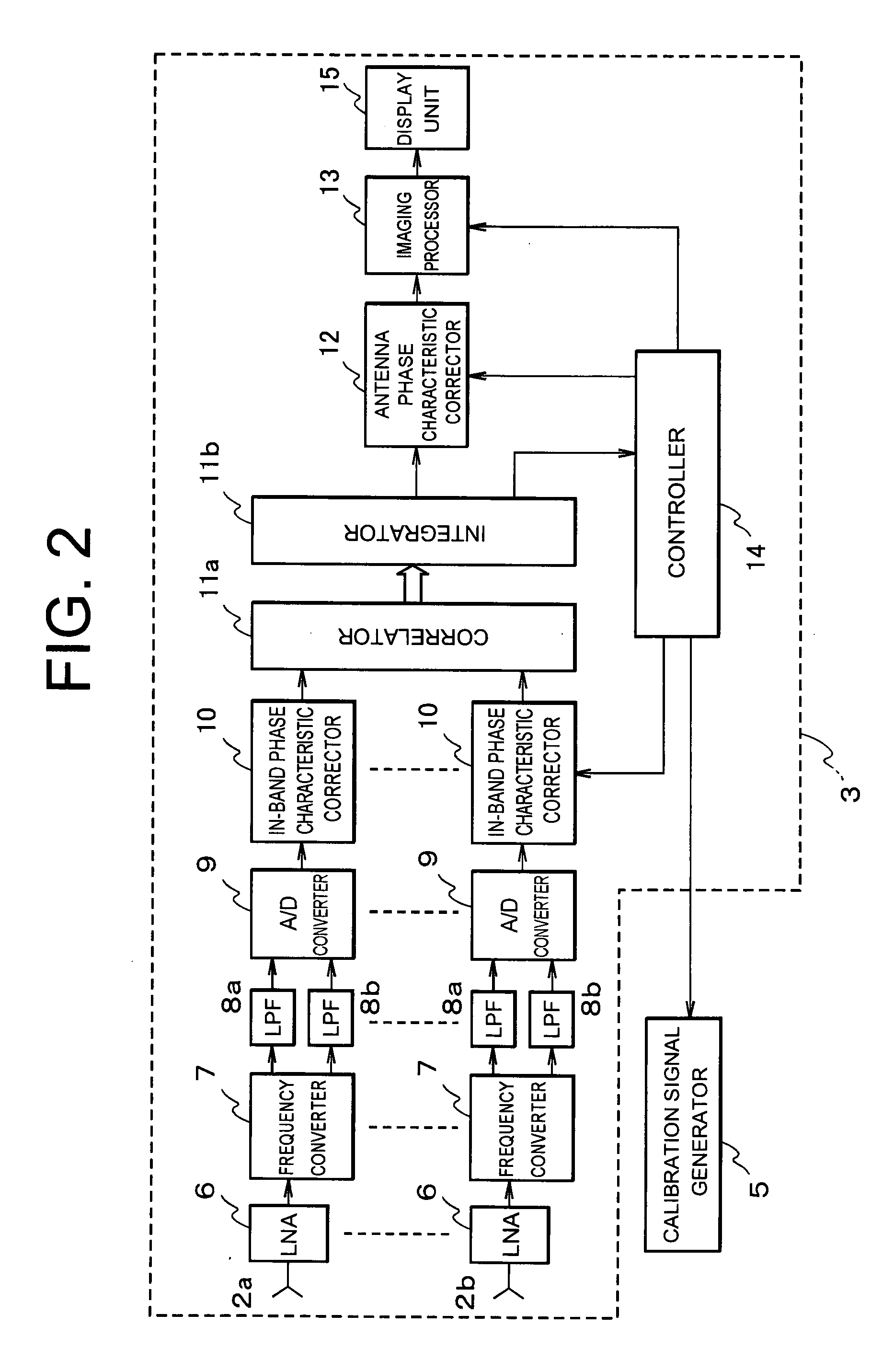
[0038]As shown in FIG. 2, a millimeter wave image processor according to an embodiment of the present invention includes a reception processing display unit 3 and a calibration signal generator 5.

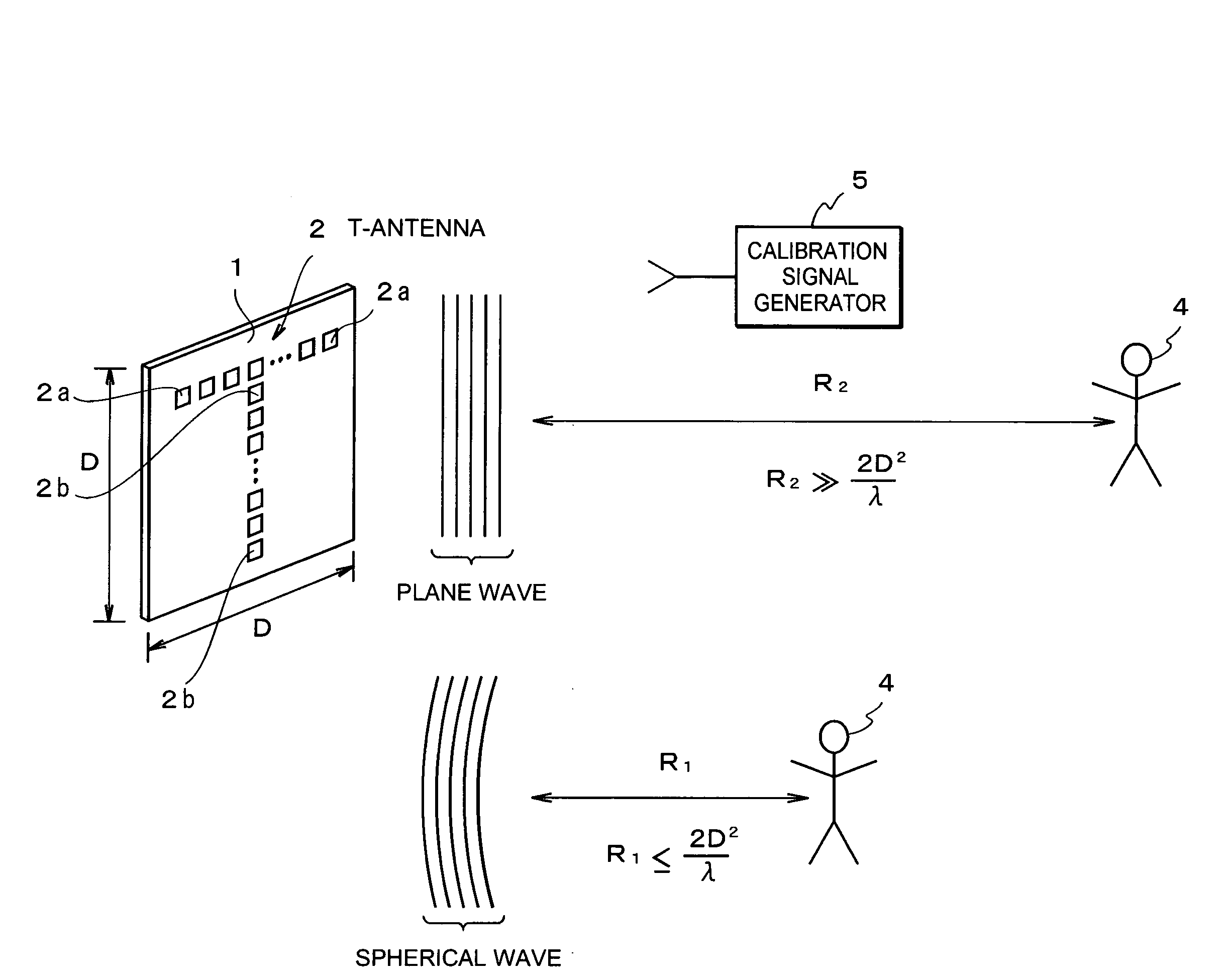
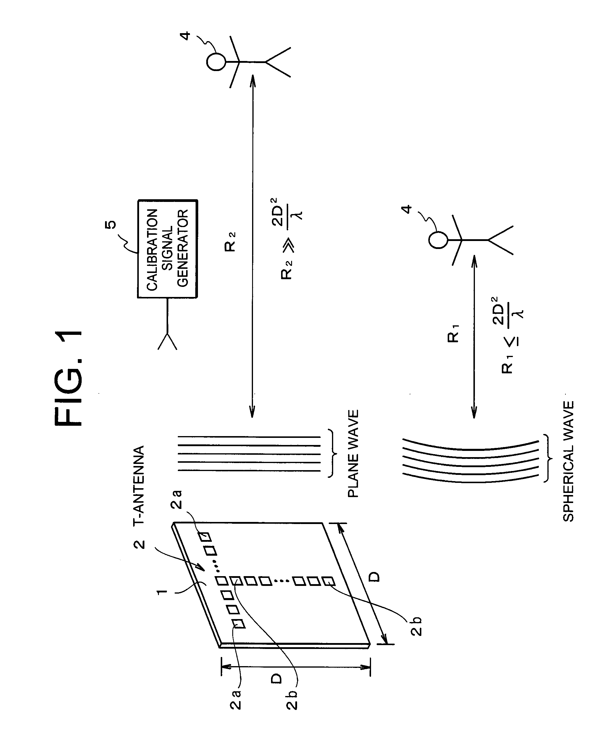
[0039]The calibration signal generator 5 is disposed at a position having a known distance from antennas 2, deployed two-dimensionally, of the reception processing display unit 3. The calibration signal generator 5 is so configured as to transmit a millimeter wave, to the antennas 2.

[0040]As shown in FIG. 1, the reception processing display unit 3 has an antenna in which a plurality of antennas 2 are arranged in T shape on an antenna face 1, as an example of most simple calibration of antennas deployed two-dimensionally. Hereinafter, the antennas 2 arranged in T shape on the antenna face 1 are collectively referred to as a T-antenna 2. The T-antenna 2 consists of a plurality of horizo...


PUM


Abstract

A millimeter wave image processor, capable of performing imaging by matching and filtering while considering a spherical wave on an antenna face in a near field, is provided. The processor includes: a T-antenna which receives a radio wave emitted by a target; an A/D converter which A/D converts signals received by the T-antenna; a correlation processing unit which performs correlation processing to a combination of signals of a horizontal conversion output and a vertical conversion output among A/D converted data; and an imaging processor which correlates a reference function in which a received signal is generated theoretically on an assumption that the target is at a position of a focused distance and a received signal of a spherical wave received by the T-antenna for each pixel in the field of view to thereby create an image of the target.

Description

BACKGROUND OF THE INVENTION[0001]1. Field of the Invention[0002]The present invention relates to a millimeter wave image processor and a millimeter wave image processing method, in which an electromagnetic wave of a millimeter wave emitted or reflected by a moving or still object is received, whereby image information of the object as a target is acquired.[0003]2. Description of Related Art[0004]A human body or the like may emit a millimeter wave together with an infrared ray. Further, every article emits and reflects an electromagnetic wave of a millimeter wave band at an intensity determined depending on the temperature and the radiative coefficient. The transparency of a millimeter wave with respect to moisture and substance is higher than the transparency of an infrared ray with respect to moisture and substance. By receiving such a millimeter wave so as to perform image processing, it is possible to monitor a target such as a distant landscape where is interrupted by fog and a ...

Claims


Application Information

Patent Timeline
IPC IPC(8): G01S13/08G01S7/02G01S13/89
CPCG01N21/3581G01S13/89G01S7/40G01V8/005
Inventor NOHMI, HITOSHI
Owner NEC CORP
Why Eureka
Try Eureka