Closely Packed Dipole Array Antenna

a dipole array antenna and dipole array technology, applied in the field of close-packed dipole array antennas, can solve problems such as tolerances of etching, and achieve the effect of low number of radar cross-section (rcs) grating lobes and easy manufactur

Inactive Publication Date: 2007-09-27
TELEFON AB LM ERICSSON (PUBL)
View PDF4 Cites 14 Cited by
  • Summary
  • Abstract
  • Description
  • Claims
  • Application Information

AI Technical Summary

Benefits of technology

[0013] It is an object of the present invention to provide a dipole array antenna where a controlled electromagnetic coupling between adjacent dipole arms of

Problems solved by technology

There is, however, still a problem with the etching tolerances in the embodiments enclosed in U.S. Pat. No. 6,512,487, especially for high frequencies.
This configuration has a drawback, since in a

Method used


Image

  • Closely Packed Dipole Array Antenna
  • Closely Packed Dipole Array Antenna
  • Closely Packed Dipole Array Antenna

Examples


Embodiment Construction

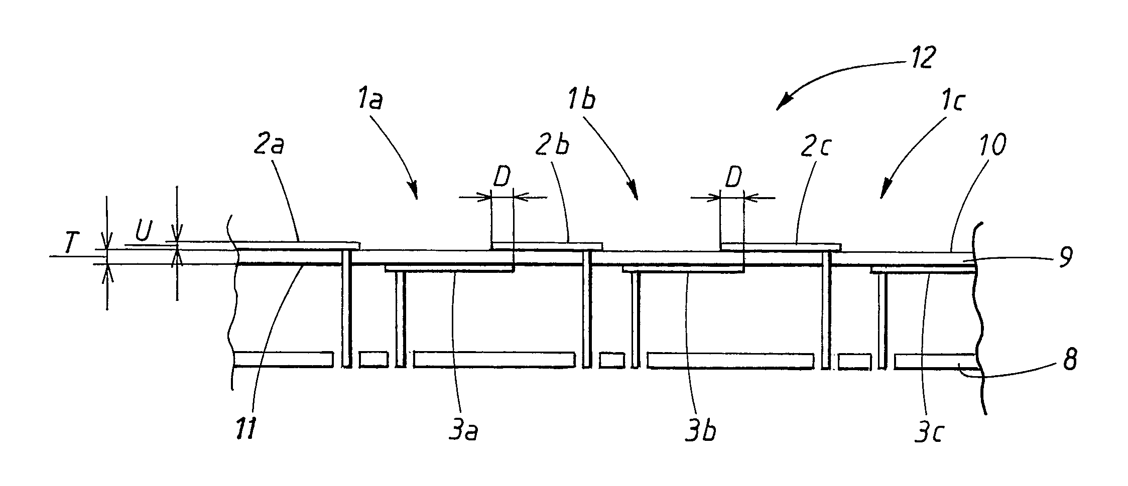
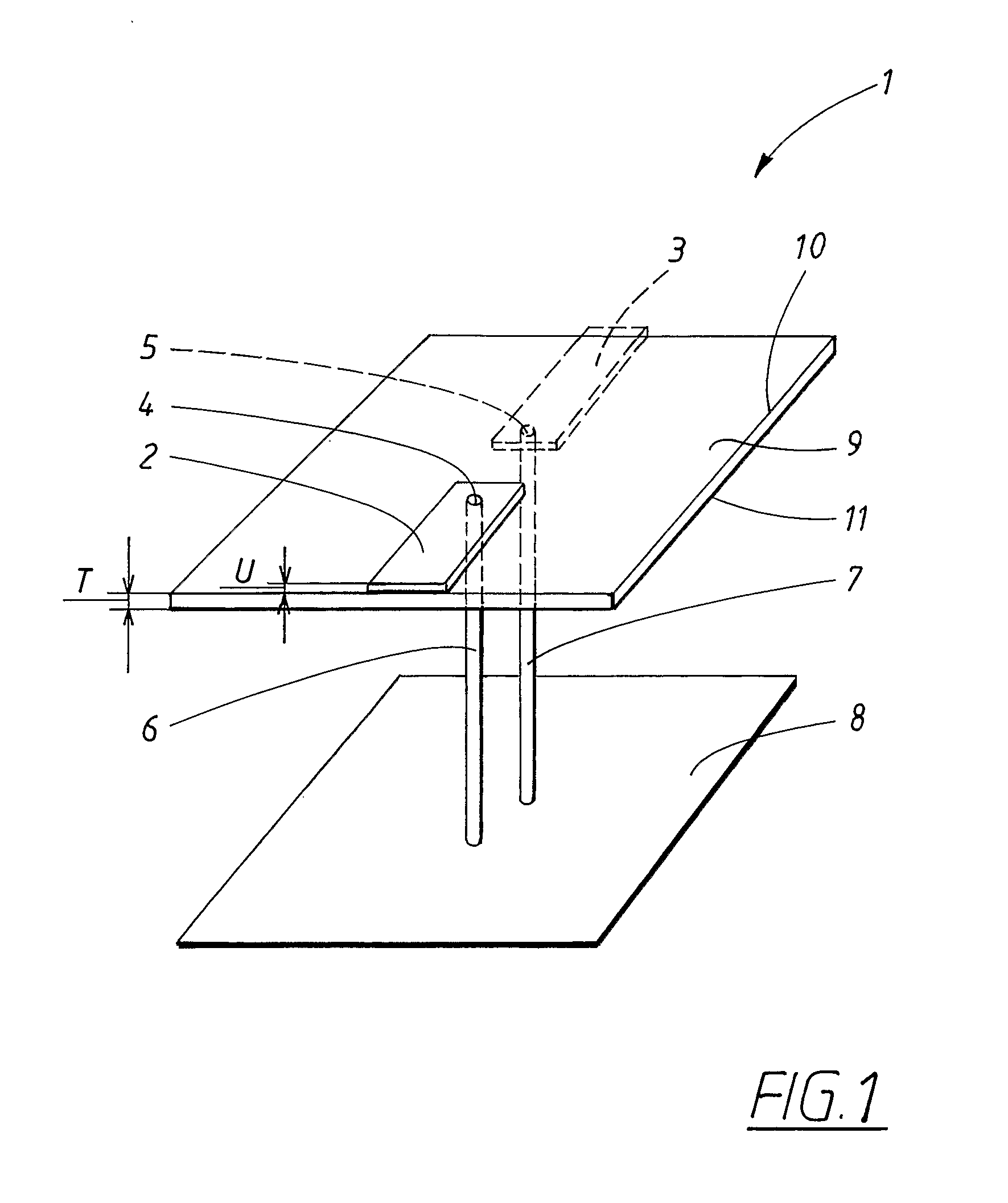
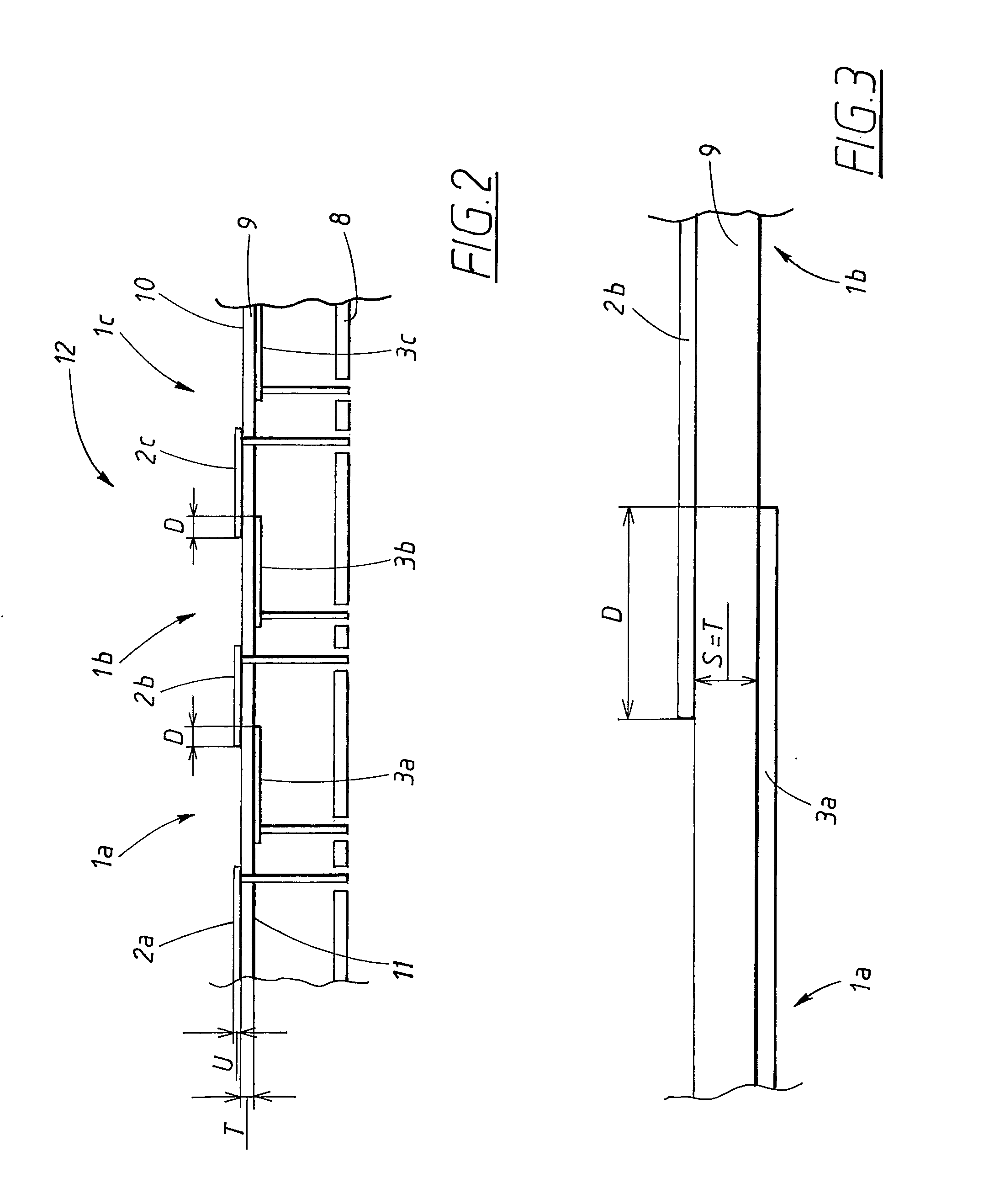
[0039] In FIG. 1, a perspective view of a dipole antenna element 1 used in the invention is shown. The dipole antenna element 1 comprises two dipole arms, a first 2 and a second 3 dipole arm, that extend in opposite directions from corresponding feeding point 4, 5 ends. The antenna element 1 comprises feeding conductors 6, 7, for example in the form of coaxial conductors extending through a ground plane 8 below the dipole antenna element 1 and up to the respective feeding point 4, 5.

[0040] The dipole arms 2, 3 have a rectangular shape and are, according to the present invention, formed on either side of a supporting laminate 9, preferably by means of etching of metal layers which are adhered to the laminate in question. The etching procedure removes all metallization, for example copper, leaving only the dipole arms. The first dipole arm 2 is formed on a first side 10 of the laminate 9, which first side 10 faces away from the ground plane 8, while the second dipole arm 3 is formed ...


PUM


Abstract

The present invention relates to an antenna device for wireless transmission and reception of information using electromagnetic signals, comprising at least two dipole antenna elements, where each dipole antenna element comprises a first dipole arm and a second dipole arm, which first and second dipole arms are extending in essentially opposite directions from a respective feeding point end. The dipole arms are formed in metal layers on a laminate, having a first side and a second side, which laminate further has a predefined thickness (T) separating the first and second side. Each first dipole arm extend on the first side of the laminate and each second dipole arm extend on the second side of the laminate in such a way that the two adjacent dipole arms of adjacent antenna elements partially overlap during a distance (D).

Description

TECHNICAL FIELD [0001] The present invention relates to an antenna device for wireless transmission and reception of information using electromagnetic signals, comprising at least two dipole antenna elements, where each dipole antenna element comprises a first dipole arm and a second dipole arm, which first and second dipole arms are extending in essentially opposite directions from a respective feeding point end, where the dipole arms are formed in metal layers on a laminate, having a first side and a second side, which laminate further has a predefined thickness separating the first and second side. BACKGROUND ART [0002] The dipole antenna element is a commonly used antenna element, which is applicable in many applications. The dipole antenna element occurs both as a separate antenna and in array antennas, and phased array antennas. The dipole antenna element comprises two conducting metal rods that usually extend in the same plane, in opposite directions from the feeding point, f...

Claims


Application Information

Patent Timeline
IPC IPC(8): H01Q21/26H01Q1/38H01Q9/28H01Q21/06
CPCH01Q1/38H01Q21/067H01Q21/062H01Q9/28
Inventor WIKSTROM, ANDREASWESTERBERG, JESSICASJOBERG, DANIEL
Owner TELEFON AB LM ERICSSON (PUBL)
Why Eureka
Try Eureka