Electro-optic media produced using ink jet printing

a technology of ink jet printing and electrophoretic media, which is applied in the field of electrophoretic media produced using ink jet printing, can solve the problems of inadequate service life of gas-based electrophoretic media, unable to meet the needs of the user, so as to reduce the cost and production lead time, and increase the cost

Active Publication Date: 2007-09-27
E INK CORPORATION
View PDF99 Cites 127 Cited by
  • Summary
  • Abstract
  • Description
  • Claims
  • Application Information

AI Technical Summary

Benefits of technology

[0086]The edge sealing material may of course be further treated after the edge seal has been formed; for example the edge sealing material may be treated with heat or radiation to effect any necessary curing of the edge sealing material. There are numerous possible ways of forming the edge seal. For example, as illustrated in FIG. 20 of the aforementioned U.S. Pat. No. 6,982,178, it may be desirable to provide one or more additional protective layers on the side of the front substrate remote from the backplane, and the edge seal may extend from the backplane to these protective layers rather than to the front substrate itself, so that the sequence of steps would be (a) ink jet print edge sealing material on peripheral portion of backplane; (b) laminate front plane laminate to backplane so that front plane laminate lies entirely within edge sealing material; and (c) place one or more protective layers on front substrate so that protective layers contact edge sealing material, thereby forming an edge seal. The edge sealing material may of course be further treated after the placement of the protective layers, for example by heat or radiation to effect any necessary curing of the edge sealing material.
[0087]A further aspect of the invention relates to the ink jet printing of electrodes and/or conductors on to a layer of electro-optic material. Although as discussed above, in most cases it is common practice to form an electro-optic display by laminating a layer of electro-optic material to a backplane containing one or more electrodes,...

Problems solved by technology

Nevertheless, problems with the long-term image quality of these displays have prevented their widespread usage.
For example, particles that make up electrophoretic displays tend to settle, resulting in inadequate service-life for these displays.
Such gas-based electrophoretic media appear to be susceptible to the same types of problems due to particle settling as liquid-based electrophoretic media, wh...

Method used


Image

  • Electro-optic media produced using ink jet printing
  • Electro-optic media produced using ink jet printing
  • Electro-optic media produced using ink jet printing

Examples


Embodiment Construction

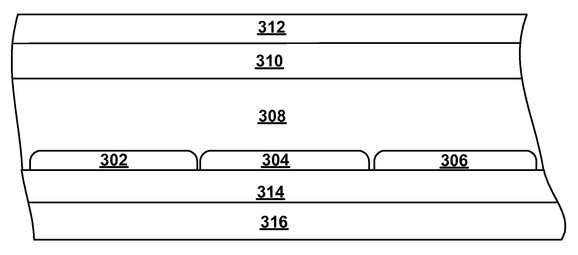
[0093]As already mentioned, the present invention provides numerous different processes in which ink jet printing is used in the production of electro-optic displays and components of such displays, especially front plane laminates and double release films. However, the numerous different processes of the invention all make use of one of the following four steps:

[0094](a) ink jet printing a layer of a polymer-dispersed electrophoretic medium on a substrate;

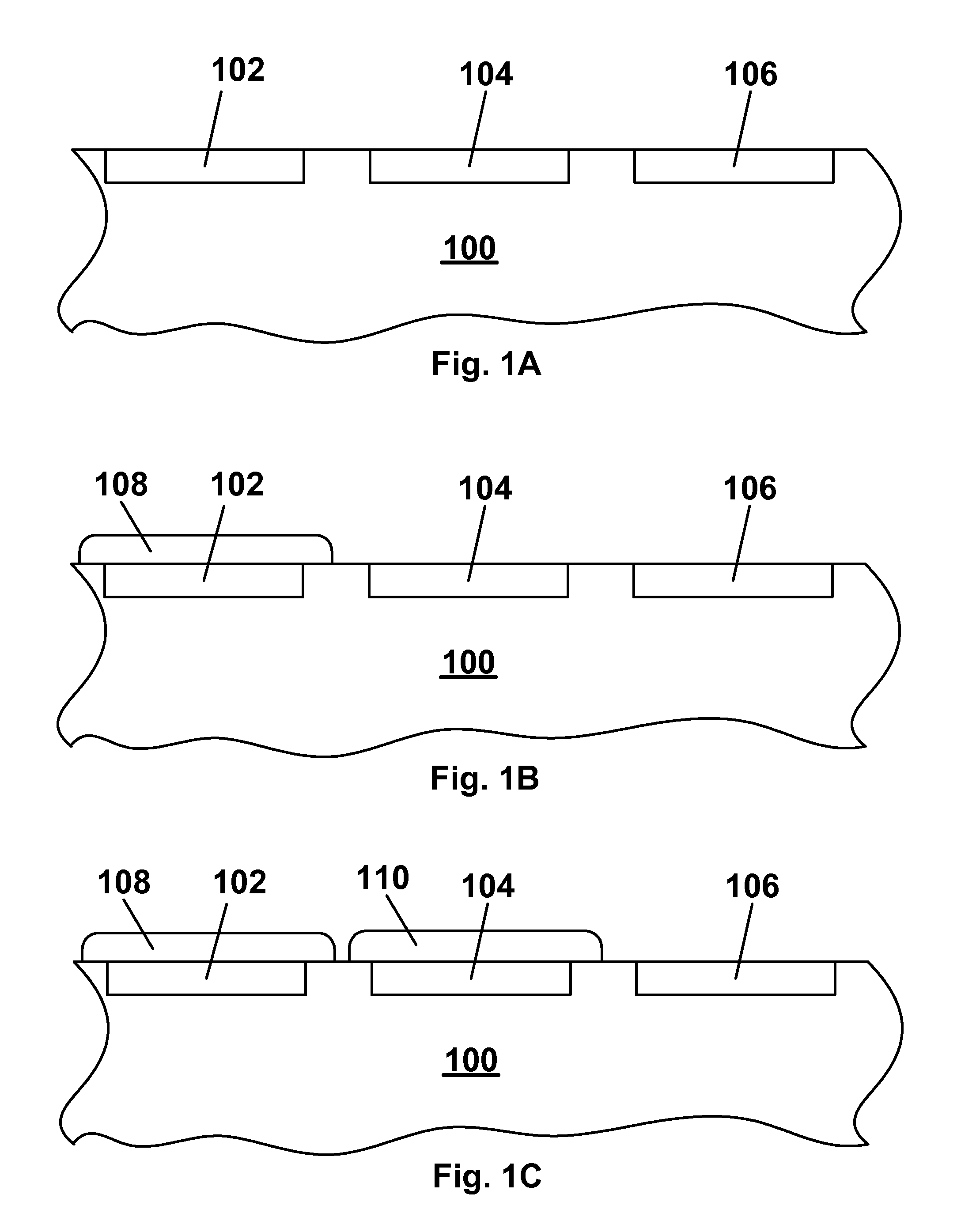
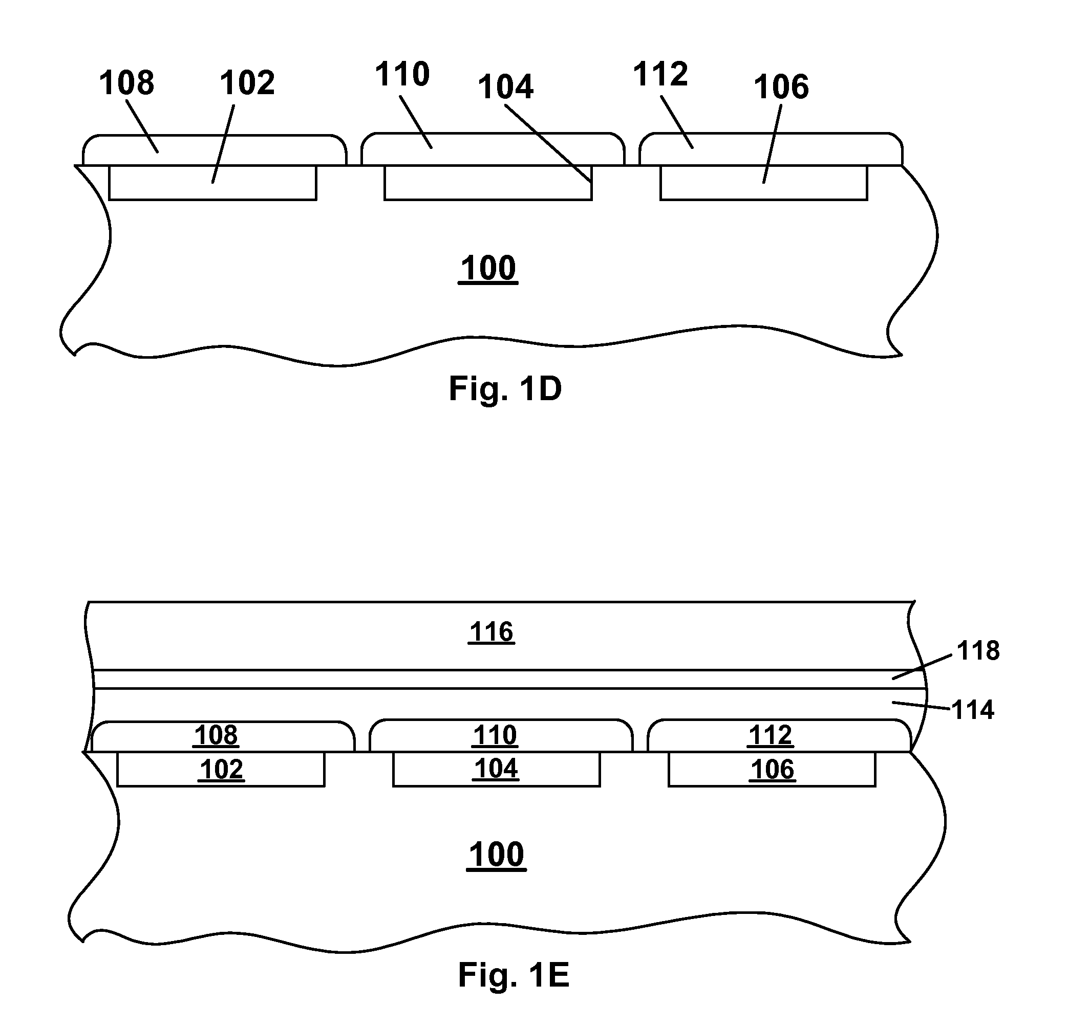
[0095](b) ink jet printing a plurality of different electro-optic media on a substrate to form a “color” electro-optic layer (in the sense of an electro-optic layer in which different areas react differently to application of an electric field);

[0096](c) ink jet printing a plurality of different colored materials on a substrate to produce a color filter (which is not necessarily a full color filter); and

[0097](d) ink jet printing electrodes and / or associated conductors on a layer of electro-optic material.

[0098]Various processes o...


PUM


Abstract

Ink jet printing can be used in the production of electro-optic displays for (a) forming a layer of a polymer-dispersed electrophoretic medium on a substrate; (b) forming a color electro-optic layer; (c) forming a color filter; and (d) printing electrodes and/or associated conductors on a layer of electro-optic material.

Description

REFERENCE TO RELATED APPLICATIONS[0001]This application claims benefit of Provisional Application Ser. No. 60 / 743,653, filed Mar. 22, 2006.[0002]This application is related to:[0003](a) U.S. Pat. No. 6,982,178;[0004](b) application Ser. No. 10 / 605,024 filed Sep. 2, 2003 (Publication No. 2004 / 0155857); and[0005](c) U.S. Pat. No. 7,110,164, issued Sep. 19, 2006 on application Ser. No. 10 / 904,063, filed Oct. 21, 2004, which claims priority from Application Ser. No. 60 / 481,553, filed Oct. 24, 2003; Application Ser. No. 60 / 481,554, filed Oct. 24, 2003; Application Ser. No. 60 / 481,557, filed Oct. 23, 2003; Application Ser. No. 60 / 481,564, filed Oct. 27, 2003; and Application Ser. No. 60 / 520,226, filed Nov. 14, 2003.[0006]The entire contents of all the aforementioned applications, and of all other United States Patents and published and copending Applications mentioned below, are also herein incorporated by reference.BACKGROUND OF INVENTION[0007]The present invention relates to electro-opt...

Claims


Application Information

Patent Timeline
IPC IPC(8): G02B26/00G02F1/167G02F1/1679
CPCG02B5/201G02F2001/1676G02F1/167G02F1/133516G02F1/1679
Inventor HONEYMAN, CHARLES HOWIEDANNER, GUY M.
Owner E INK CORPORATION
Why Eureka
Try Eureka