
Surface light source, backlight unit and liquid crystal display having the same

a backlight unit and liquid crystal display technology, applied in the direction of threaded fasteners, lighting and heating apparatus, instruments, etc., can solve the problems of large light loss, insufficient illumination of light generated at the light source b>12, etc., to prevent heat from being easily transferred, reduce production costs, and reduce the effect of electric power consumption

Inactive Publication Date: 2007-09-27
LG ELECTRONICS INC
View PDF7 Cites 19 Cited by
  • Summary
  • Abstract
  • Description
  • Claims
  • Application Information

AI Technical Summary

Benefits of technology

[0018]An object of the present invention is to provide a surface light source device that can be easily manufactured.
[0019]Another object of the present invention is to provide a surface light source device that consumes low electric power and that is free of the heat-related problems.
[0020]Further another object of the present invention is to provide a surface light source device that is easily applicable to large size and thin display devices.

Problems solved by technology

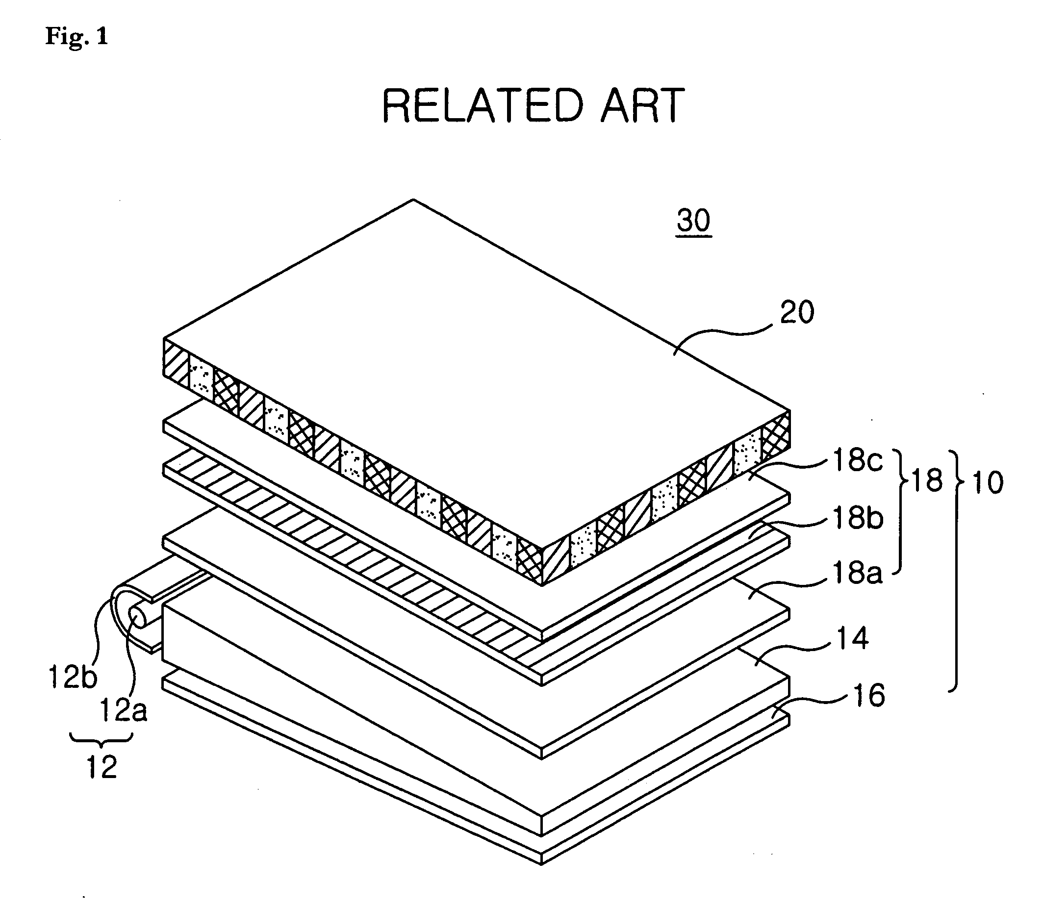
However, the edge-light type backlight unit 10, which only uses the light that is input through the side surfaces of the light guide plate for illumination, has a problem that the light generated at the light source 12 is not fully used for illumination because the light loss occurs considerably at the light guide plate 14.
Furthermore, the direct type backlight unit, which has a plurality of light sources positioned directly under the liquid crystal panel, also has a problem that the light loss occurs at optical plates such as a diffusion plate.
The deformation of the optical sheets deteriorates the display quality.
However, the surface light source devices of the above publications still suffer from one or more of the following disadvantages: the complex manufacturing process, unsatisfactory optical property, and high power consumption.

Method used


Image

  • Surface light source, backlight unit and liquid crystal display having the same
  • Surface light source, backlight unit and liquid crystal display having the same
  • Surface light source, backlight unit and liquid crystal display having the same

Examples


Embodiment Construction

[0042]Further scope of applicability of the present invention will become apparent from the detailed description given hereinafter. However, it should be understood that the detailed description and specific examples, while indicating preferred embodiments of the invention, are given by way of illustration only, since various changes and modifications within the spirit and scope of the invention will become apparent to those skilled in the art from this detailed description.

[0043]In the following drawings, the same reference numbers will be used to refer to the same or like parts through all embodiments. In addition, the detailed descriptions of the identical parts are not repeated.

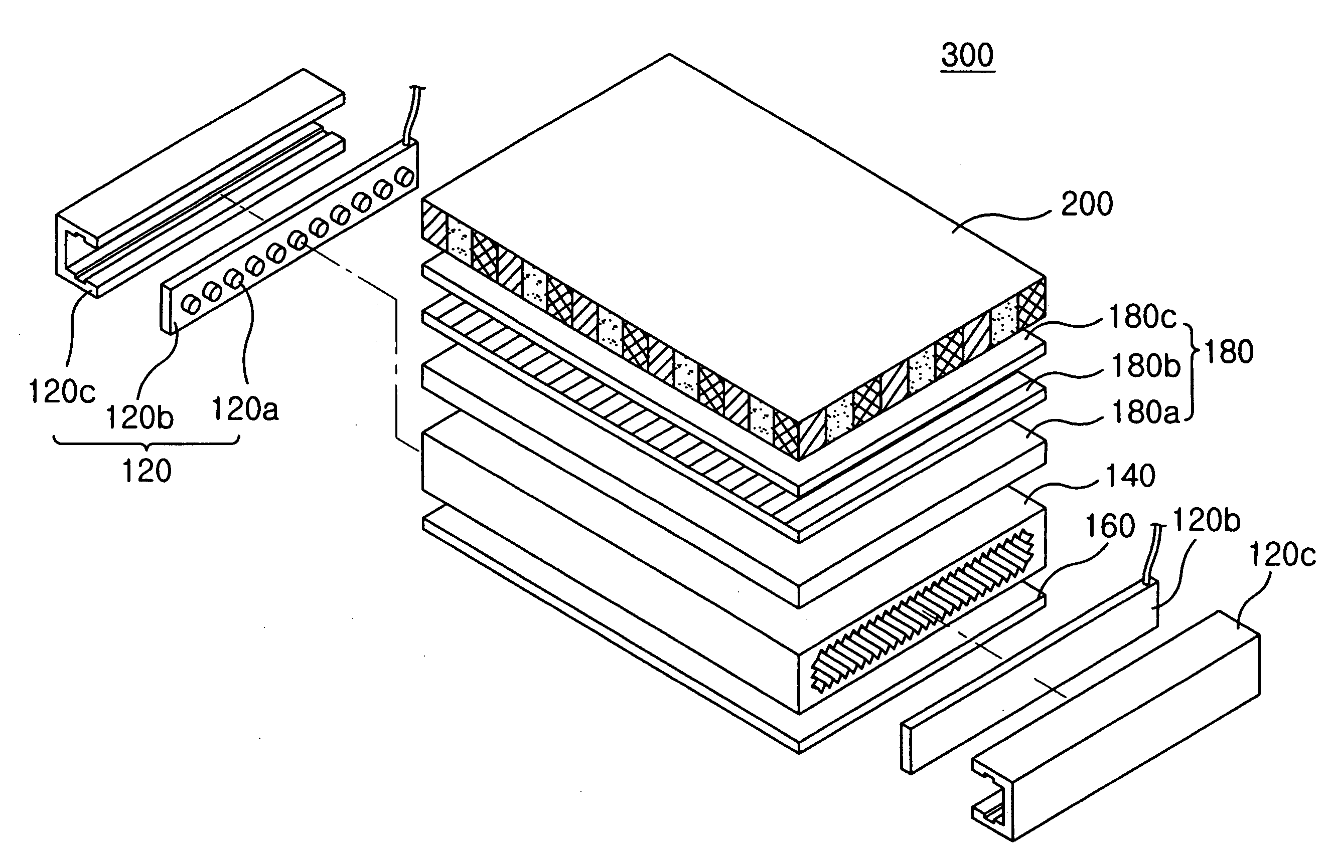
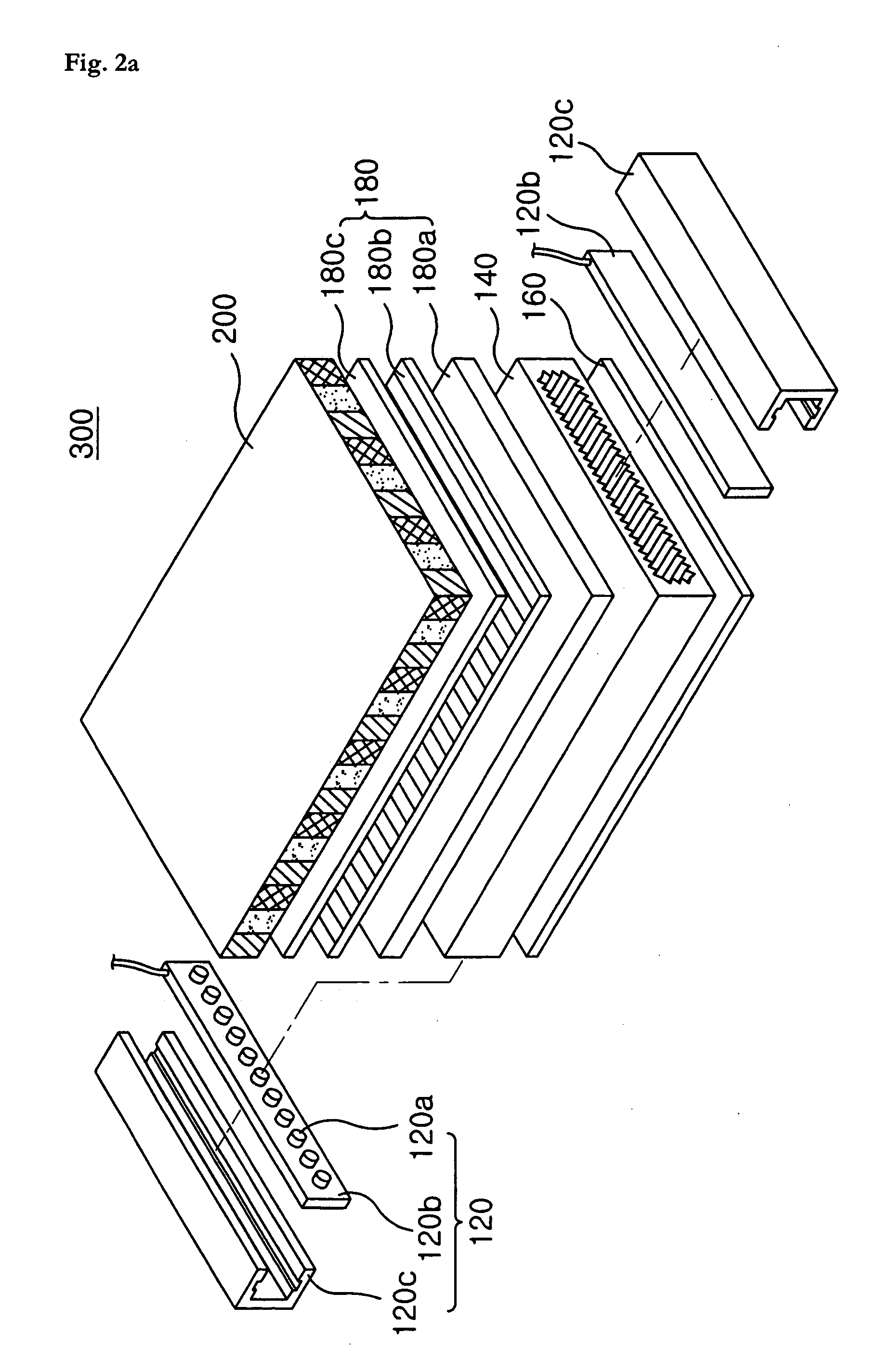
[0044]FIG. 2a is an exploded perspective view illustrating a liquid crystal display according to one embodiment of the present invention; and FIG. 2b is a cross-sectional view illustrating the liquid crystal display of FIG. 2a.

[0045]Referring to FIGS. 2a and 2b, a liquid crystal panel 300 according to th...


PUM


Abstract

The present invention is directed to a surface light source utilizing a light pipe. The present invention is also directed to a backlight unit and a liquid crystal display which are provided with such surface light source. The light pipe includes an inner surface structured with a plurality of prisms, wherein the light from the light source is incident on the inner surface; and a smooth outer surface having a light emitting surface disposed substantially parallel to the liquid crystal panel, wherein the incident light is emitted through the light emitting surface.

Description

CROSS-REFERENCE TO A RELATED APPLICATION[0001]The present application claims the benefit of priority under 35 U.S.C. 119 based on the Korean patent application number 10-2006-0026962 filed on Mar. 24, 2006. This application is incorporated herein by reference.BACKGROUND OF THE INVENTION[0002]1. Field of the Invention[0003]The present invention is directed to a surface light source device utilizing a light pipe. The present invention is also directed to a backlight unit and a liquid crystal display which are provided with such surface light source device.[0004]2. Description of the Related Art[0005]The liquid crystal display, also know as LCD, is an electronic device that transforms electrical signals into visual signals by utilizing the change in the transmittance of the liquid crystals according to applied voltages.[0006]As well known in the art, the liquid crystal display is a non-emitting display device. Therefore, the liquid crystal display needs to use an outside light source u...

Claims


Application Information

Patent Timeline
IPC IPC(8): F21V7/04
CPCG02B6/0038G02B6/0051G02F1/133615G02B6/0096G02B6/0055F16B37/00E21D21/0033E21D21/0093
Inventor LEE, WEON WOONG
Owner LG ELECTRONICS INC
Learn More