Dispersion compensation type optical signal receiving apparatus, receiving circuit, receiving method, and receiving program

Inactive Publication Date: 2007-09-27
NEC CORP
View PDF2 Cites 9 Cited by
  • Summary
  • Abstract
  • Description
  • Claims
  • Application Information

AI Technical Summary

Benefits of technology

[0028]The present invention can provide an excellent dispersion compensation type optical signal receiving apparatus, a receiving circuit, a receiving method, and a receiving program, which have not been achieved conventionally. It is possible with the above-described structures of the present invention: to eliminate the risk of loosing the information indicating the influence of the l

Problems solved by technology

Thus, the waveform of an optical signal at the input of the receiver is distorted, and the pulse width is widened, thereby deteriorating the receiving quality.
Pr

Method used


Image

  • Dispersion compensation type optical signal receiving apparatus, receiving circuit, receiving method, and receiving program
  • Dispersion compensation type optical signal receiving apparatus, receiving circuit, receiving method, and receiving program
  • Dispersion compensation type optical signal receiving apparatus, receiving circuit, receiving method, and receiving program

Examples


Embodiment Construction

[0034]An embodiment of the present invention will be described hereinafter by referring to the accompanying drawings.

Structure

[0035]The overall constitution will be described first, and the specific structures will be described thereafter.

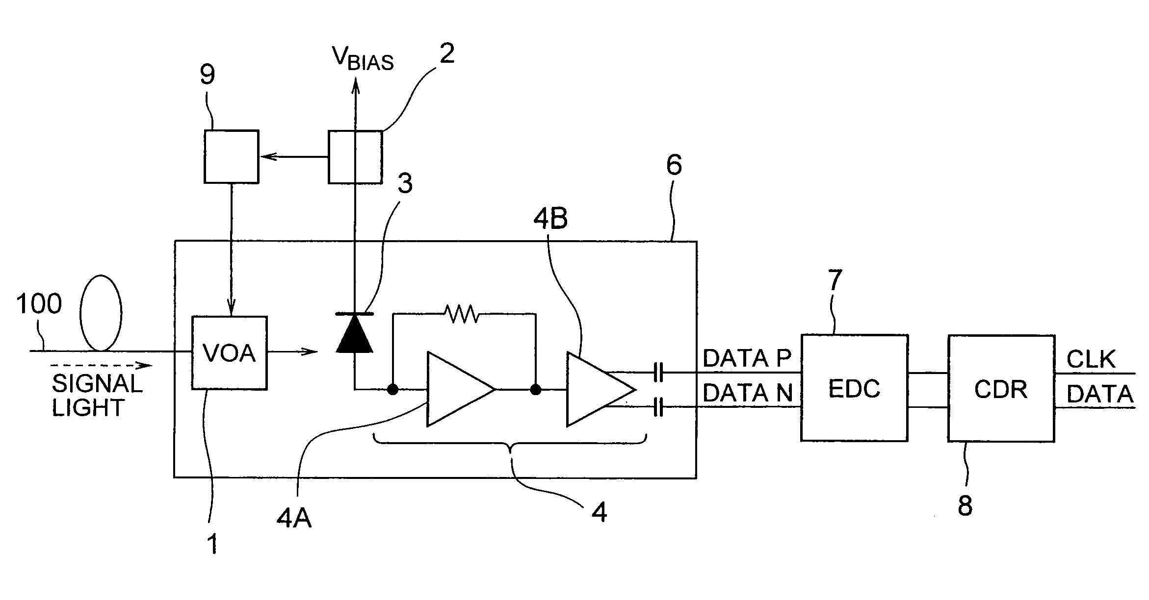
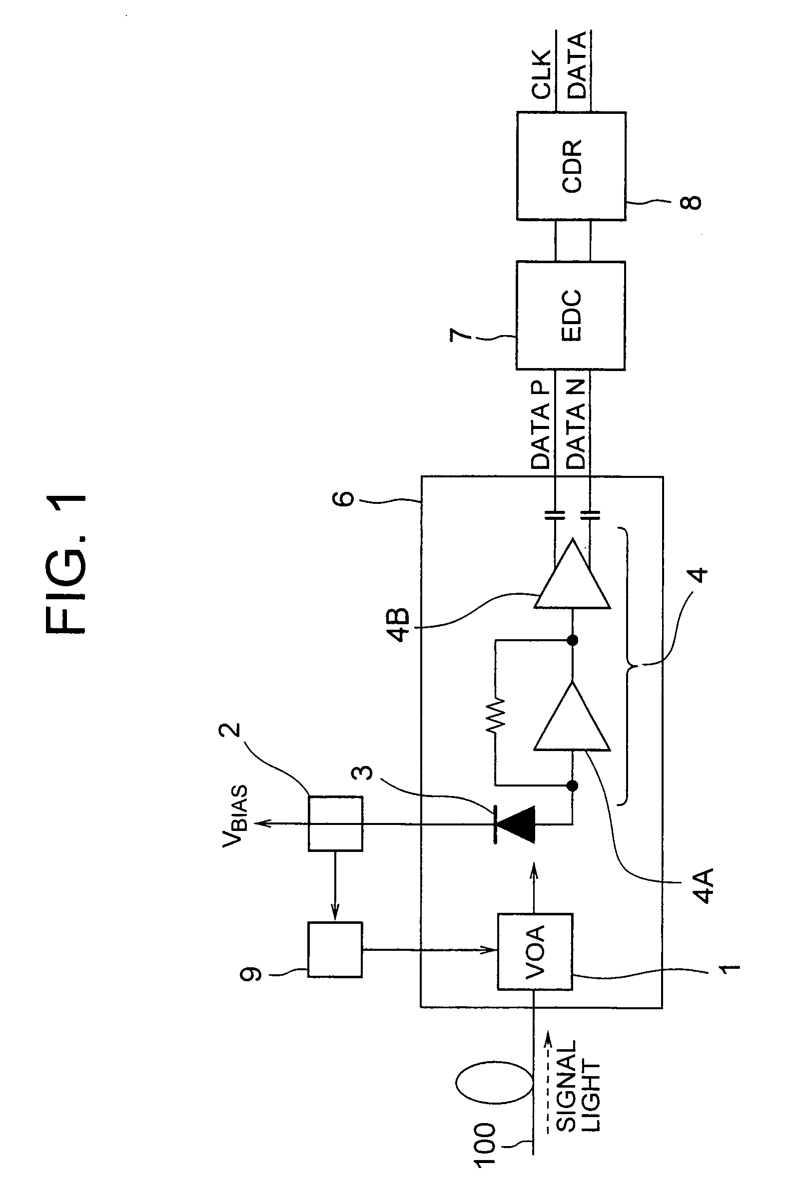
[0036]First, the dispersion compensation type optical signal receiving apparatus according to this embodiment comprises: an APD (Avalanche Photodiode) element 3 as a photoelectric converting device for converting the input signal light inputted from an optical transmission line 100 into an electric signal; an amplifying device 4 for amplifying the electric signal that is converted by the APD element (photoelectric converting device) 3; an EDC (Electronic Dispersion Compensation) IC 7 as an electronic dispersion compensation device for electrically compensating the dispersion in the optical transmission line 100; and a clock / data reproducing circuit (CDR) 8 as a signal reproducing device for reproducing the signal of the data and the like contained...


PUM


Abstract

To obtain a dispersion compensation type optical signal receiving apparatus constituted in such a manner that an electric signal outputted from a light receiving module can be properly inputted to an electronic dispersion compensation IC without being distorted, even when the input level of the optical signal is high. The dispersion compensation type optical signal receiving apparatus comprises: an APD element for converting input signal light inputted from a transmission line into an electric signal; an amplifying device constituted with a preamplifier circuit and a limit amplifier circuit, which amplifies the electric signal converted by the APD element; an EDC IC for compensating the dispersion in the transmission line electrically; and a clock/data reproducing circuit for reproducing the clock and data signal contained in the input signal light, wherein there is provided a VOA for limiting the amplitude of the input signal light inputted to the APD element and an attenuation amount controlling circuit for controlling the attenuation amount of the VOA in accordance with the bias current of the APD element.

Description

BACKGROUND OF THE INVENTION[0001]1. Field of the Invention[0002]The present invention relates to a dispersion compensation type optical signal receiving apparatus used for optical communications and, more specifically, to a dispersion compensation type optical signal receiving apparatus, a receiving circuit, a receiving method, and a receiving program, which are capable of avoiding saturation of a limiter amplifier circuit.[0003]2. Description of the Related Art[0004]The refractive index of the core of the optical fibers differs depending on the wavelength, so that light is propagated at a different speed in accordance with its wavelength. This phenomenon is called dispersion, and the reaching time of the light to a receiver differs for each wavelength because of this phenomenon. Thus, the waveform of an optical signal at the input of the receiver is distorted, and the pulse width is widened, thereby deteriorating the receiving quality. In order to compensate the dispersion opticall...

Claims


Application Information

Patent Timeline
IPC IPC(8): H04B10/12H04B10/2507H01L31/10H04B10/07H04B10/2525H04B10/293H04B10/40H04B10/50H04B10/564H04B10/572H04B10/60H04B10/67H04B10/69
CPCH04B10/66H03F3/08
Inventor UCHIKATA, TATSUYA
Owner NEC CORP
Why Eureka
Try Eureka