Power management and control in electronic equipment

a technology of electronic equipment and power management, applied in secondary cells, emergency power supply arrangements, instruments, etc., can solve the problems of sudden consumption of power, power consumption of large amounts, and inability to perform power management and control corresponding to actual system load, etc., and achieve the effect of efficient power supply

Inactive Publication Date: 2007-09-27
LG ELECTRONICS INC
View PDF2 Cites 38 Cited by
  • Summary
  • Abstract
  • Description
  • Claims
  • Application Information

AI Technical Summary

Benefits of technology

[0015]Accordingly, an object of the present invention is to provide an apparatus and method for power management and control in portable electronic equipment, wherein efficient power supply can be achieved according to consuming power of a system load, output power of a fuel cell, and a charged remaining capacity of a battery.

Problems solved by technology

If the fuel cell and the battery cannot supply power required by the portable electronic equipment, a main body of the computer is forcibly shut down.
However, in the WO 2005 / 003941 system, the fuel cell controller acquires the amount of power required by the portable electronic equipment, i.e., load information of a central processing unit (CPU), which is recognized by OS, via a system bus to recognize desired system power and then recognizes the desired amount of power, i.e., consuming power information, based on task scheduling.
That is, it is impossible to perform power management and control corresponding to an actual system load.
Typically, in portable electronic equipment such as a portable computer, much power is consumed suddenly when several tasks are simultaneously processed by an optical disk driver (ODD), a floppy disk driver (FDD), and the like.
Accordingly, this causes user's inconvenience in using the portable electronic equipment.
The BIOS may limit the performance of the system in response to a performance limit signal (PLS) output from the control unit.

Method used


Image

  • Power management and control in electronic equipment
  • Power management and control in electronic equipment
  • Power management and control in electronic equipment

Examples


Embodiment Construction

[0034]Hereinafter, an apparatus for power management in portable electronic equipment will be described in detail with reference to the accompanying drawings. It should be noted that the following description is exemplary only and that the present invention is not limited to the disclosed embodiment but may be implemented in different forms. Further, it should be noted that in the following description, detailed descriptions of functions and configurations known in the art, which may make the subject matter of the present invention obscure, will be omitted.

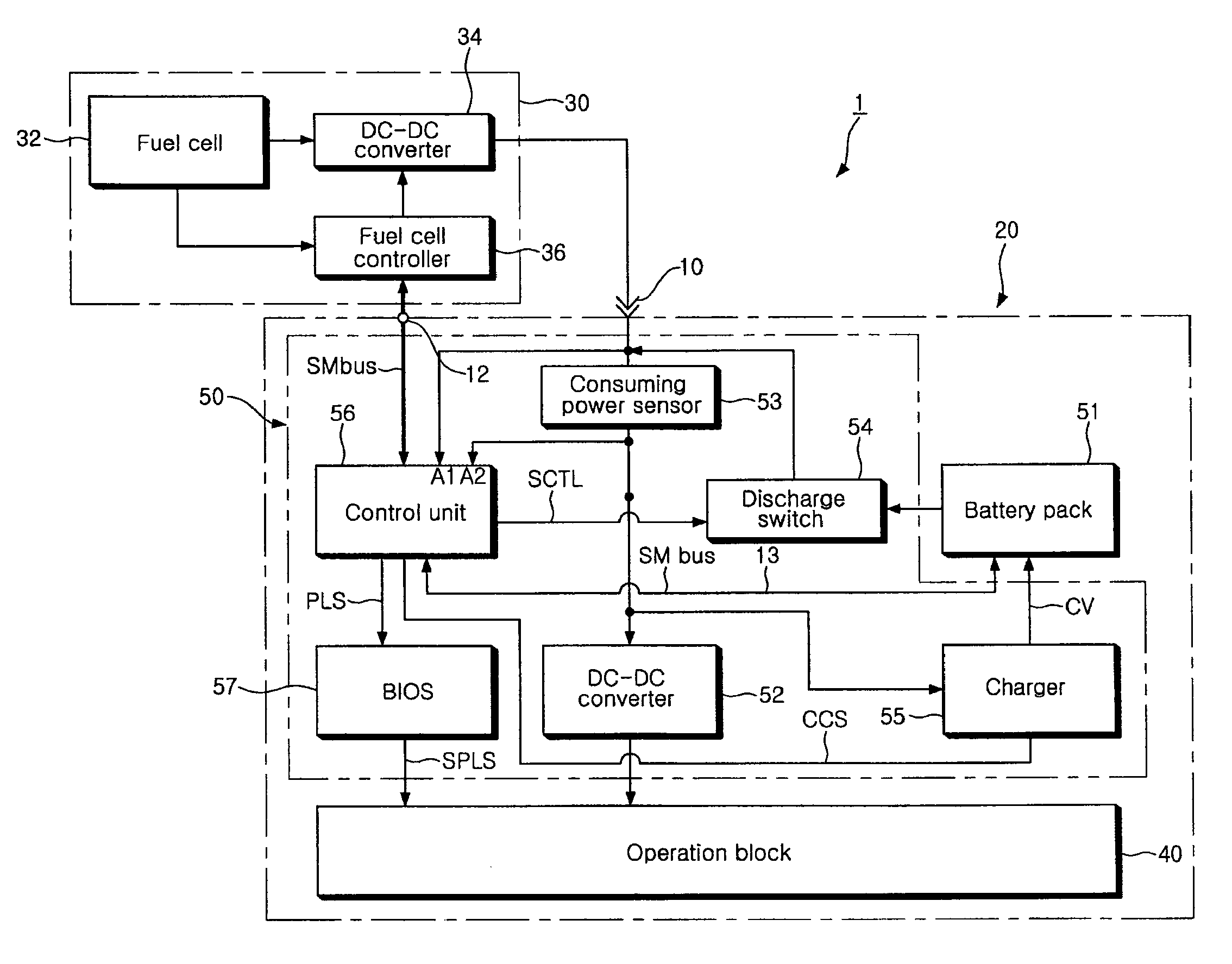
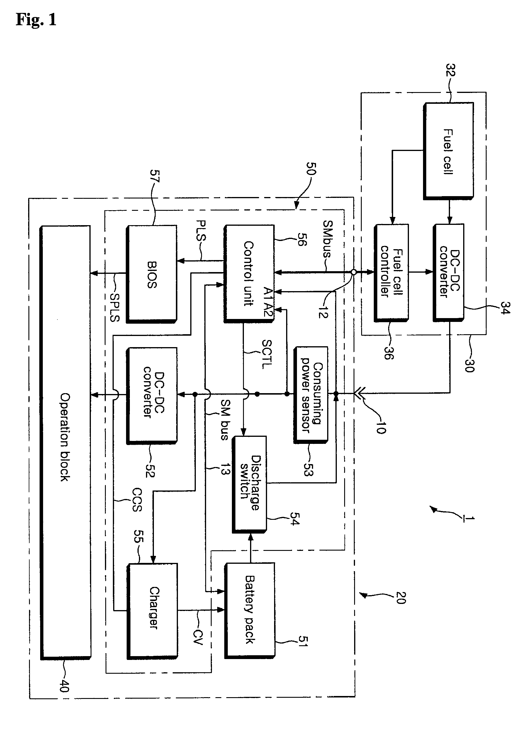
[0035]FIG. 1 is a block diagram illustrating portable electronic equipment 1 that employs a power management and control apparatus according to a preferred embodiment of the present invention. Referring to FIG. 1, the portable electronic equipment 1 according to the present invention comprises a system main body 20 with a battery pack 51 coupled thereto, and a fuel cell pack 30 connected to a power input terminal 10 and a bus conn...


PUM

PropertyMeasurementUnit
poweraaaaaaaaaa
frequencyaaaaaaaaaa
voltageaaaaaaaaaa

Abstract

To manage power of a fuel cell and a battery for an electronic device, an amount of power consumed by an operation module in the electronic device may be sensed. Generated voltage capacity of the fuel cell and remaining capacity of the battery may be acquired. The battery may be charged / discharged based on the sensed amount of consumed power and the generated voltage capacity of the fuel cell. A performance limit signal may be provided to the operation module if the sensed amount of consumed power exceeds a sum of the generated voltage capacity of the fuel cell and the remaining capacity of the battery. The operation module may adjust a frequency of an internal operation clock in response to the performance limit signal.

Description

BACKGROUND[0001]1. Field[0002]The present invention relates to an apparatus and method for power management and control in portable electronic equipment, and more particularly, to an apparatus and method for power management and control of a battery pack or a fuel cell pack for generating a voltage when the fuel cell pack is connected to portable electronic equipment having an operation block driven by a driving voltage of the battery pack.[0003]2. Description of Related Art[0004]With the recent development of electrical and electronic communication and electrochemistry-related industries, portable electronic equipment such as laptop computers, and personal digital assistants (PDAs) is typically driven by a voltage of a battery. For this reason, there have been conducted researches on a longer life span of a battery. Of course, when the equipment is provided with an AC-adaptor that converts commercial power (AC power) into a DC voltage, the equipment does not require such a battery ...

Claims


Application Information

Patent Timeline
Patent Type & Authority Applications(United States)
IPC IPC(8): H01M16/00H01M8/04H02J7/00
CPCG06F1/263
Inventor OH, JANG GEUN
Owner LG ELECTRONICS INC
Why Eureka
Try Eureka