Connector resiliently deformed easily with small load and method of manufacturing the same

a resilient connection and small load technology, applied in the field of connectors, can solve the problems of difficult soldering of solder balls to the wiring board, complicated assembly of resilient connections, and difficult manufacturing of resilient connections, and achieve the effects of simple structure, high density, and advantageous shielding function

Inactive Publication Date: 2007-09-27
NEC CORP
View PDF49 Cites 4 Cited by
  • Summary
  • Abstract
  • Description
  • Claims
  • Application Information

AI Technical Summary

Benefits of technology

[0026] It is therefore an object of the present invention to provide a connector resiliently deformable with a small load, high in density, simple in structure, and advantageous in having a shielding function, and also to provide a method of manufacturing the connector.

Problems solved by technology

As a result, soldering of the solder balls to the wiring board becomes difficult.
Reduction in thickness of the resilient connections 89, however, makes manufacturing of the resilient connections 89 difficult, and also makes assembly of the resilient connections 89 complicated.

Method used


Image

  • Connector resiliently deformed easily with small load and method of manufacturing the same
  • Connector resiliently deformed easily with small load and method of manufacturing the same
  • Connector resiliently deformed easily with small load and method of manufacturing the same

Examples


first embodiment

[0052] With reference to FIGS. 7 and 8, a connector according to the present invention will now be described.

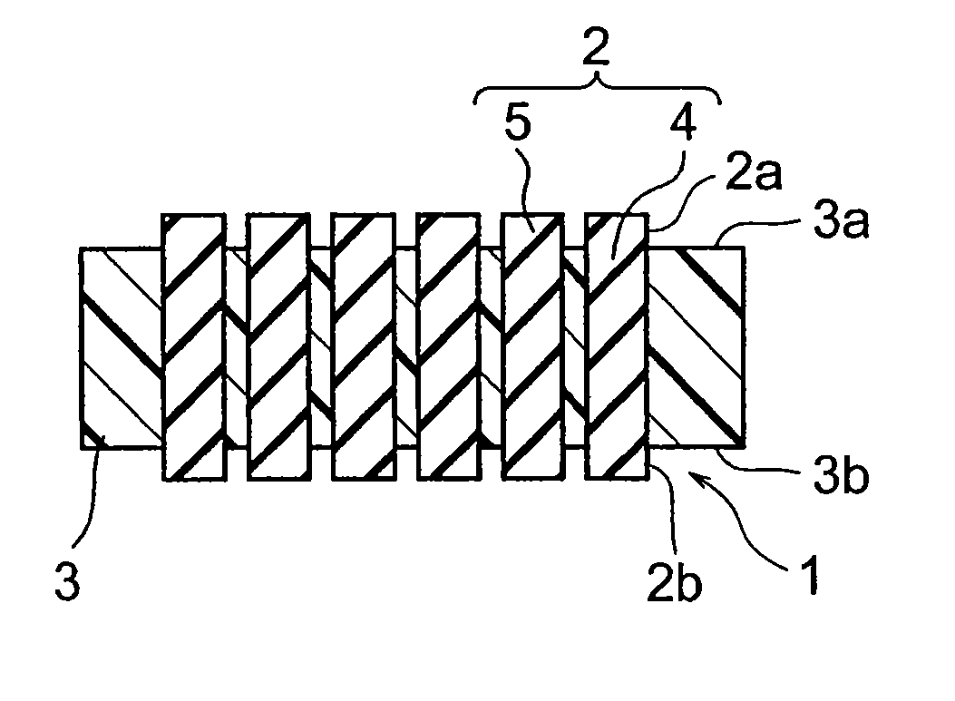
[0053] In FIGS. 7 and 8, a reference numeral 1 indicates the connector. In the connector 1, a multitude of electrodes 2 arrayed in a square lattice pattern are held by a support member 3 in a central region thereof. In the present example, the electrodes 2 are arrayed in the square lattice pattern. The electrodes 2, however, are not limited to any particular array. For example, the electrodes 2 may be arrayed in a houndstooth pattern or at random.

[0054] Each of the electrodes 2 includes projections 2a and 2b, which project from a front surface 3a and a rear surface 3b of the support member 3, respectively. The front surface 3a and the rear surface 3b are parallel to each other. Each of the electrodes 2 further includes a component 4 of a column shape (e.g., a cylindrical column or a rectangular column) formed of a resilient material, such as a rubber and a gel, and a metal t...

second embodiment

[0071] With reference to FIG. 20, a connector according to the present invention will now be described.

[0072] The respective electrodes 2 of the connector 1 are bent. With the electrodes 2 thus bent, the electrodes 2 are deformed not only by simple compression but also by bending. Accordingly, the electrodes 2 can further flexibly respond to the variation in flatness of the contact surface.


PUM

PropertyMeasurementUnit
sizeaaaaaaaaaa
thermosettingaaaaaaaaaa
thicknessaaaaaaaaaa

Abstract

A connector includes a support member and a plurality of electrodes. The support member is of a plate shape and has a front surface and a rear surface. Each of the electrodes pierces through the support member to have projections which project from the front surface and the rear surface, respectively. Each of the electrodes includes a component of a column shape formed of a resilient material and a metal thin film formed on a surface of the component.

Description

[0001] This application is a Divisional of U.S. patent application Ser. No. 11 / 404,084, entitled CONNECTOR RESILIENTLY DEFORMED EASILY WITH SMALL LOAD AND METHOD OF MANUFACTURING THE SAME, filed Apr. 14, 2006, which is hereby incorporated by reference in its entirety. [0002] This application claims priority to prior application JP 2005-116515, the disclosure of which is incorporated herein by reference.BACKGROUND OF THE INVENTION [0003] The present invention relates to a connector suitable for connecting a semiconductor integrated circuit element, such as a microprocessor and an application specific integrated circuit (ASIC), and to a method of manufacturing the connector. [0004] With the advancement of the semiconductor processing technology, the integration degree of the semiconductor integrated circuit element, such as the microprocessor and the ASIC, has been increasingly improved every year. Accordingly, the number of input-output terminals of the semiconductor integrated circu...

Claims


Application Information

Patent Timeline
Patent Type & Authority Applications(United States)
IPC IPC(8): H01R12/00B29D99/00
CPCH01R13/2414
Inventor UMEZAWA, KAZUHIKOHAMAGUCHI, TETSUYASUZURIKAWA, JUNNAKANO, MICHIKI
Owner NEC CORP
Why Eureka
Try Eureka