Apparatus and Method for Light Control in an in-Vivo Imaging Device

an in-vivo imaging and apparatus technology, applied in the field of apparatus and light control in in-vivo imaging devices, can solve the problems of limited dynamic range, overexposure of the bright underexposure of the dark parts of the field of view, so as to achieve the effect of controlling and making the treatment more efficien

Active Publication Date: 2007-09-27
GIVEN IMAGING LTD
View PDF45 Cites 93 Cited by
  • Summary
  • Abstract
  • Description
  • Claims
  • Application Information

AI Technical Summary

Benefits of technology

[0010] Some embodiments of the present invention include a device and method for operating an in vivo imaging device wherein the illumination produced by the device may be varied in intensity and/or...

Problems solved by technology

One of the limitations of electronic imaging sensors is that they may have a limited dynamic range.
Thus, when the imaged field of view includes both dark and bright parts or imaged objects, the limited dynamic range of the imaging sensor may result in underexposure of the...

Method used


Image

  • Apparatus and Method for Light Control in an in-Vivo Imaging Device
  • Apparatus and Method for Light Control in an in-Vivo Imaging Device
  • Apparatus and Method for Light Control in an in-Vivo Imaging Device

Examples


Embodiment Construction

[0036] Various aspects of the present invention are described herein. For purposes of explanation, specific configurations and details are set forth in order to provide a thorough understanding of the present invention. However, it will also be apparent to one skilled in the art that the present invention may be practiced without the specific details presented herein. Furthermore, well known features may be omitted or simplified in order not to obscure the present invention.

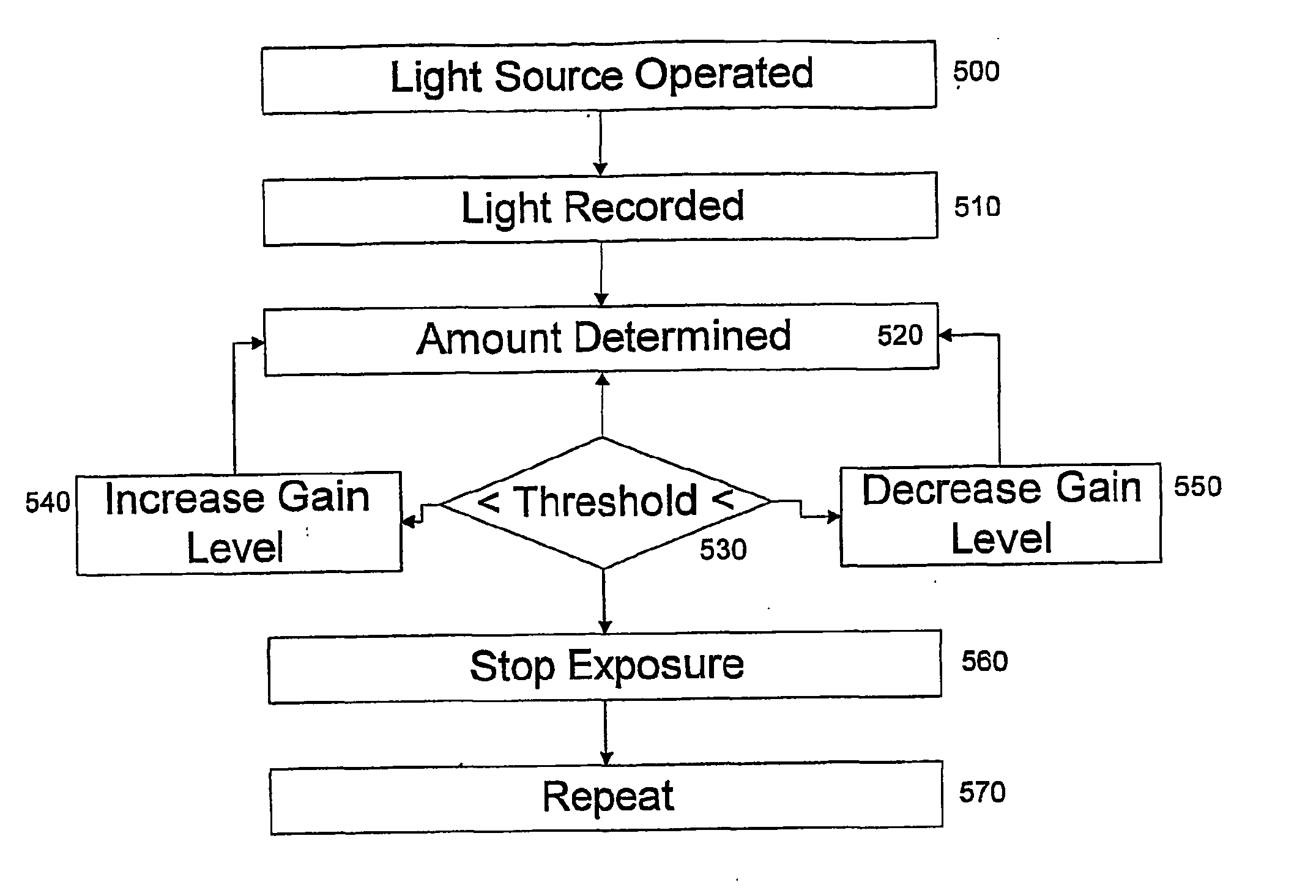
[0037] Some embodiments of the present invention are based, inter alia, on controlling the illumination provided by the in-vivo imaging device based on light measurement which is performed within the duration of a single frame acquisition time or a part thereof.

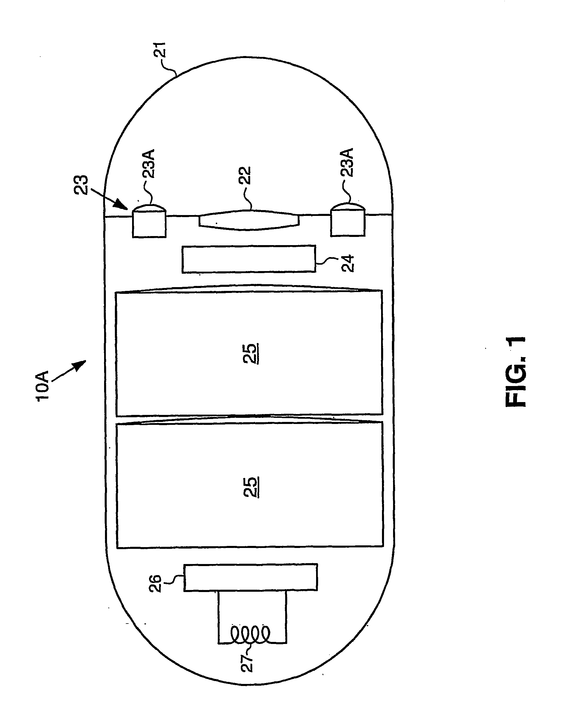
[0038] It is noted that while the embodiments of the invention shown hereinbelow are adapted for imaging of the gastrointestinal (GI) tract, the devices and methods disclosed herein may be adapted for imaging other body cavities or spaces.

[0039] Referen...


PUM


Abstract

A device and method for operating an in vivo imaging device (10A) wherein the illumination produced by the device may be varied in intensity and/or duration, and/or the gain level or other parameters may be varied, according to, for example, the amount of illumination produced by the device which is reflected back to the device. In addition, a method is provided for detecting problematic pixels in an imaging device. This method may define and exclude non-functional pixels, based on for example an initial short exposure that enables a threshold saturation level to be reached only for problematic pixels. Moreover, a method is described for determining when an in vivo device enters the body, for example by calculating the progress of a dark frame, based on the light saturation threshold of the dark frame.

Description

BACKGROUND OF THE INVENTION [0001] Devices and methods for performing in-vivo imaging of passages or cavities within a body are known in the art. Such devices may include, inter alia, various endoscopic imaging systems and devices for performing imaging in various internal body cavities. [0002] Reference is now made to FIG. 1 which is a schematic diagram illustrating an embodiment of an autonomous in-vivo imaging device. The device 10A typically includes an optical window 21 and an imaging system for obtaining images from inside a body cavity or lumen, such as the GI tract. The imaging system includes an illumination unit 23. The illumination unit 23 may include one or more discrete light sources 23A, or may include only one light source 23A. The one or more light sources 23A may be a white light emitting diode (LED), or any other suitable light source, known in the art. The device 10A includes a CMOS imaging sensor 24, which acquires the images and an optical system 22 which focuse...

Claims


Application Information

Patent Timeline
IPC IPC(8): A61B1/06
CPCA61B1/00006A61B1/00009A61B1/00057A61B1/2736A61B1/045A61B1/0684A61B1/041A61B1/000095
Inventor AVNI, DOVGLUKHOVSKY, ARKADY
Owner GIVEN IMAGING LTD
Why Eureka
Try Eureka