Automated flowback and information system

a flowback and information system technology, applied in the field of oil and gas wells, can solve the problems of complex flowback process, short and uncomplicated cleanup period, and general corrosive and abrasive fluids, and achieve the effect of quick, economical and efficient system

Inactive Publication Date: 2007-10-04
CANADIAN FRACMASTER
View PDF29 Cites 27 Cited by
  • Summary
  • Abstract
  • Description
  • Claims
  • Application Information

AI Technical Summary

Benefits of technology

[0020]An advantage of the present invention is that it is a quick, economical, and efficient system; yet still able to contain extreme pressures and abrasives traveling at high velocities.
[0021]Another advantage of the present invention is the ability of the blast barrel to retract between two fixed points for disassembly giving the user access to internal parts for replacement or inspection without having to dismantle the high-pressure fixed lines.
[0022]Yet another advantage of the present invention is that the system can be programmed to operate and function automatically from a control office or command center.

Problems solved by technology

The fluids are generally corrosive and abrasive because they are frequently laden with corrosive acids and abrasive propellants such as sharp sand, shale, coal or the like.
Depending on the treatment, the cleanup period can be short and uncomplicated.
However, in more complicated and complex larger fracturing jobs the flowback process can become much more complex and hazardous.
There are many problems associated with the conventional methods and practices used to flowback a well using current industry standards, equipment or methods.
One such problem is the installation of flowlines that connect or mate from a horizontal position to a targeted tee then to a vertical targeted tee, then back to line laying in the horizontal position on the ground.
The problem occurs because the distance and heights vary from location to location for various reasons, terrain, equipment configuration, styles, and placement of the wellhead and the surface casing.
Because of weather elements such as rain, wind, mud, snow, and cold, this function cannot be performed in an optimum environment so the quality and safety of the work performed could be compromised.
Other common problems that occur during installation are that many variables exist, such as lines that attach to choke manifolds or flowback tanks and earthed pits, all require variable lengths to mate connections.
There are other problems, such as current flowbacks do not have a way to contain the pressures or corrosive acids and abrasive propellants such as sharp sand.
The problem arises because the propellant fluids, acids, chemicals, and fracture products pumped into the wellbore formation during (flowback) clean up, travel at high velocity causing washing out of the lines and equipment from the inside out.
The current flowback practices have no method or system to contain, control or monitor a washout.
In addition, there is not a system that detects a washout or a warning system to notify when a potential washout might occur.
When this event occurs, gases, propellants, fluids, acids, and chemicals could vent to the atmosphere causing unsafe conditions, injury and environmental contamination.

Method used


Image

  • Automated flowback and information system
  • Automated flowback and information system
  • Automated flowback and information system

Examples


Embodiment Construction

)

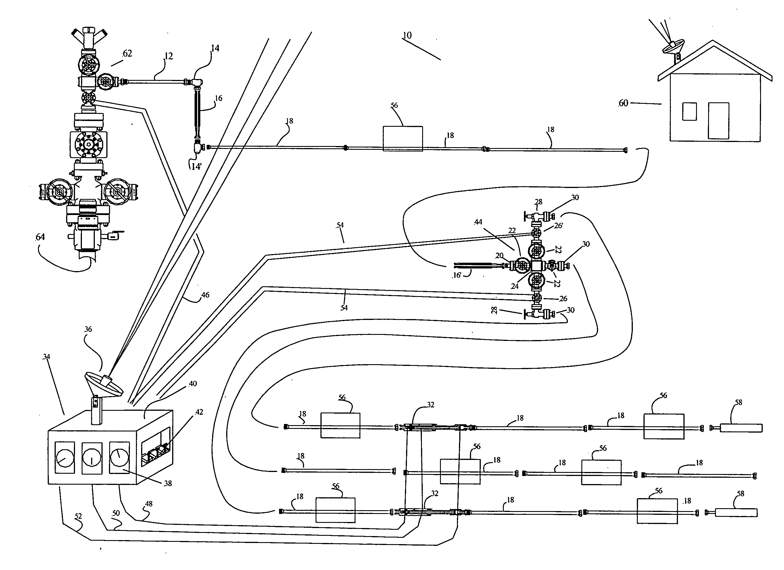
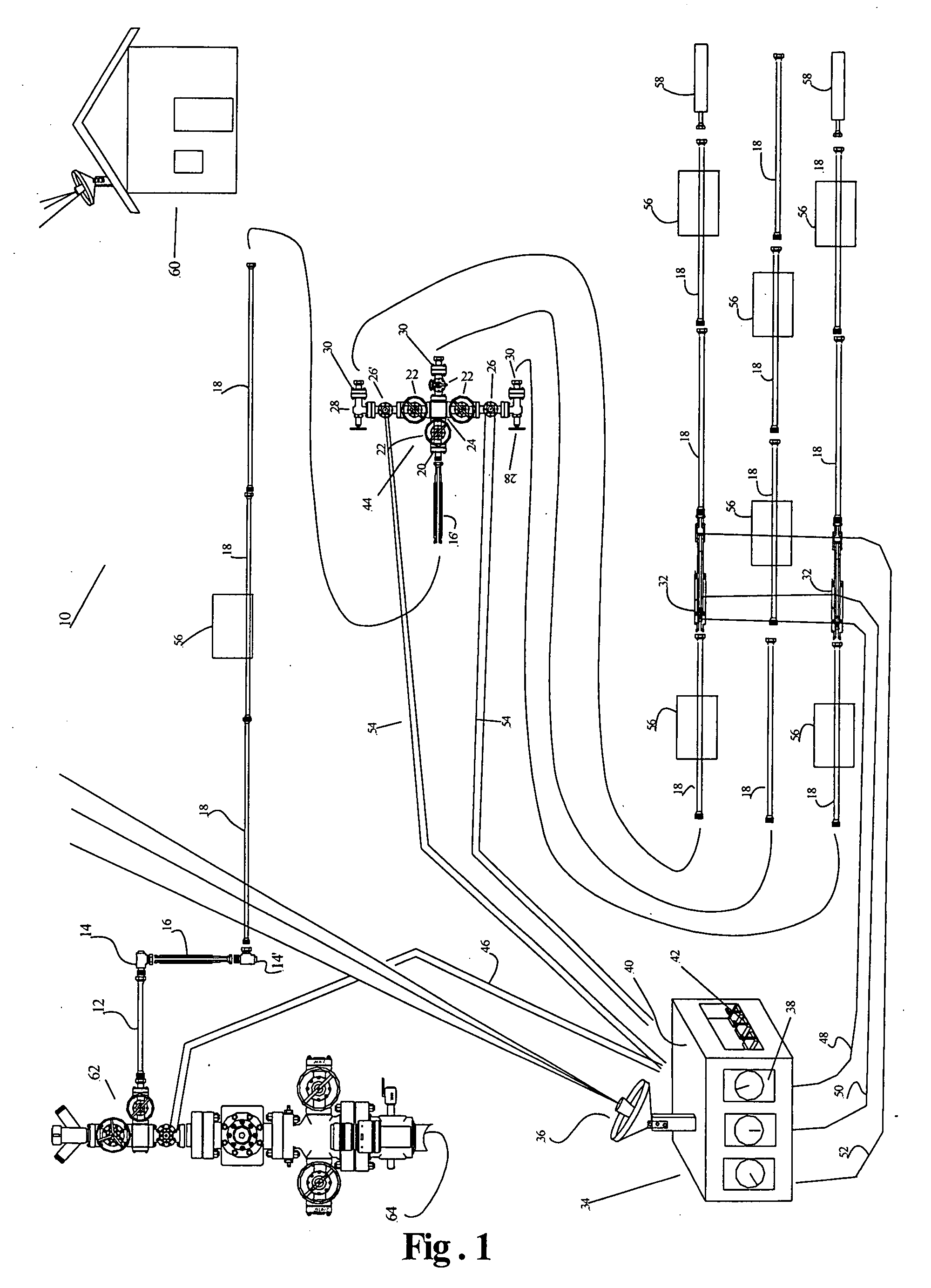
[0028]FIG. 1 shows an overall view of the equipment and component parts as assembled in a complete field installation hereinafter referred to as a flowback system 10. Flowback system 10 includes a frac tree or flowback tree 62 which include a series of valves that can be of various sizes and pressure ratings used in opening and closing the well 64 before and after fracturing stimulation and flowback clean up of a well. A high-pressure flowline, pup joint or sub 12 of various sizes and pressure ratings are installed in a horizontal position, and vary in length based on the application. High-pressure flowlines 12 are typically attached or installed by a connection, known in the oil and gas industry, as a hammer union (not shown). These connections are made by rotating the wingnut portion of the union onto the threaded portion of the union, and connected to integral union cushion elbow or targeted tee 14. The integral union cushion elbow 14 is designed to absorb and deflect the produc...


PUM


Abstract

An automated flowback system allows control and operation of the system from a remote location away from the dangers of high-pressure gases or abrasives traveling at high velocities that cause damage or failure to equipment piping valves. The system provides techniques and mechanical components installed in flowlines in any position without having to cut and thread, weld or fabricate pipe to fit. This system includes an expansion sub with axial adjusting lengths adequate to compensate for variations between two points. The expansion sub is secured and installed into position eliminating field cut and threading, welding or fabrication. The system also includes a blast barrel with an installed choke nipple, choke bean or choke insert with a chosen orifice size for multiple chambered ports. The blast barrel retracts between two fixed points without having to dismantle any connections or be removed from the fluid flow.

Description

CROSS-REFERENCE TO RELATED APPLICATIONS[0001]This application is based on U.S. Provisional Application Ser. No. 60 / 787,456, entitled “Automated Flowback and Information System” filed on Mar. 30, 2006, the teachings of which are incorporated herein by reference.BACKGROUND OF THE INVENTION[0002]1. Field of the Invention (Technical Field):[0003]The present invention relates to oil and gas wells, and more particularly to a system for providing a controlled flowback from the wellbore after a treatment procedure.[0004]2. Background Art[0005]Most oil and gas wells require some form of stimulation to enhance hydrocarbon flow to make or keep them economically viable. The servicing of oil and gas wells to stimulate production requires the pumping of fluids under high-pressure. The fluids are generally corrosive and abrasive because they are frequently laden with corrosive acids and abrasive propellants such as sharp sand, shale, coal or the like.[0006]The components which make up the wellhead...

Claims


Application Information

Patent Timeline
Patent Type & Authority Applications(United States)
IPC IPC(8): E21B43/12
CPCE21B34/00E21B43/25E21B43/12E21B37/00Y10T137/0402
Inventor ATENCIO, DON
Owner CANADIAN FRACMASTER
Why Eureka
Try Eureka