Laser-driven light source

a laser-driven light source and laser-driven technology, which is applied in the direction of photomechanical equipment, instruments, nuclear engineering, etc., can solve the problems of insufficient brightness of arc lamps, unstable position of arc lamps, and failure of light sources, so as to minimize the cooling of ionized medium and substantially continuous high-brightness light

Active Publication Date: 2007-10-04
HAMAMATSU PHOTONICS KK
View PDF5 Cites 140 Cited by
  • Summary
  • Abstract
  • Description
  • Claims
  • Application Information

AI Technical Summary

Benefits of technology

[0016] In some embodiments, the at least one laser is a continuous wave laser or a high pulse rate laser. In some embodiments, the at least one laser is a high pulse rate laser that provides pulses of energy to the ionized medium so the high brightness light is substantially continuous. In some embodiments, the magnitude of the high brightness light does not vary by more than about 90% during operation. In some embodiments, the at least one laser provides energy substantially continuously to minimize cooling of the ionized medium when energy is not provided to the ionized medium.

Problems solved by technology

As a result, the anode and / or cathode are prone to wear and may emit particles that can contaminate the light source or result in failure of the light source.
Also, these arc lamps do not provide sufficient brightness for some applications, especially in the ultraviolet spectrum.
Further, the position of the arc can be unstable in these lamps.

Method used


Image

  • Laser-driven light source
  • Laser-driven light source
  • Laser-driven light source

Examples


Embodiment Construction

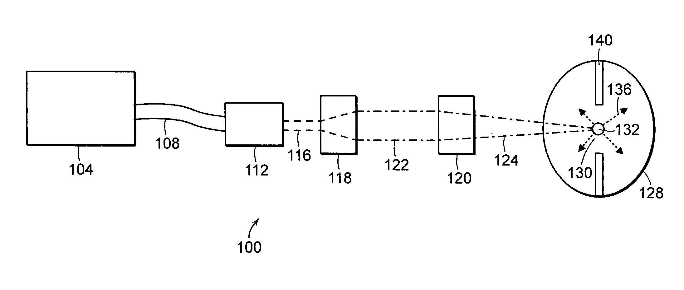
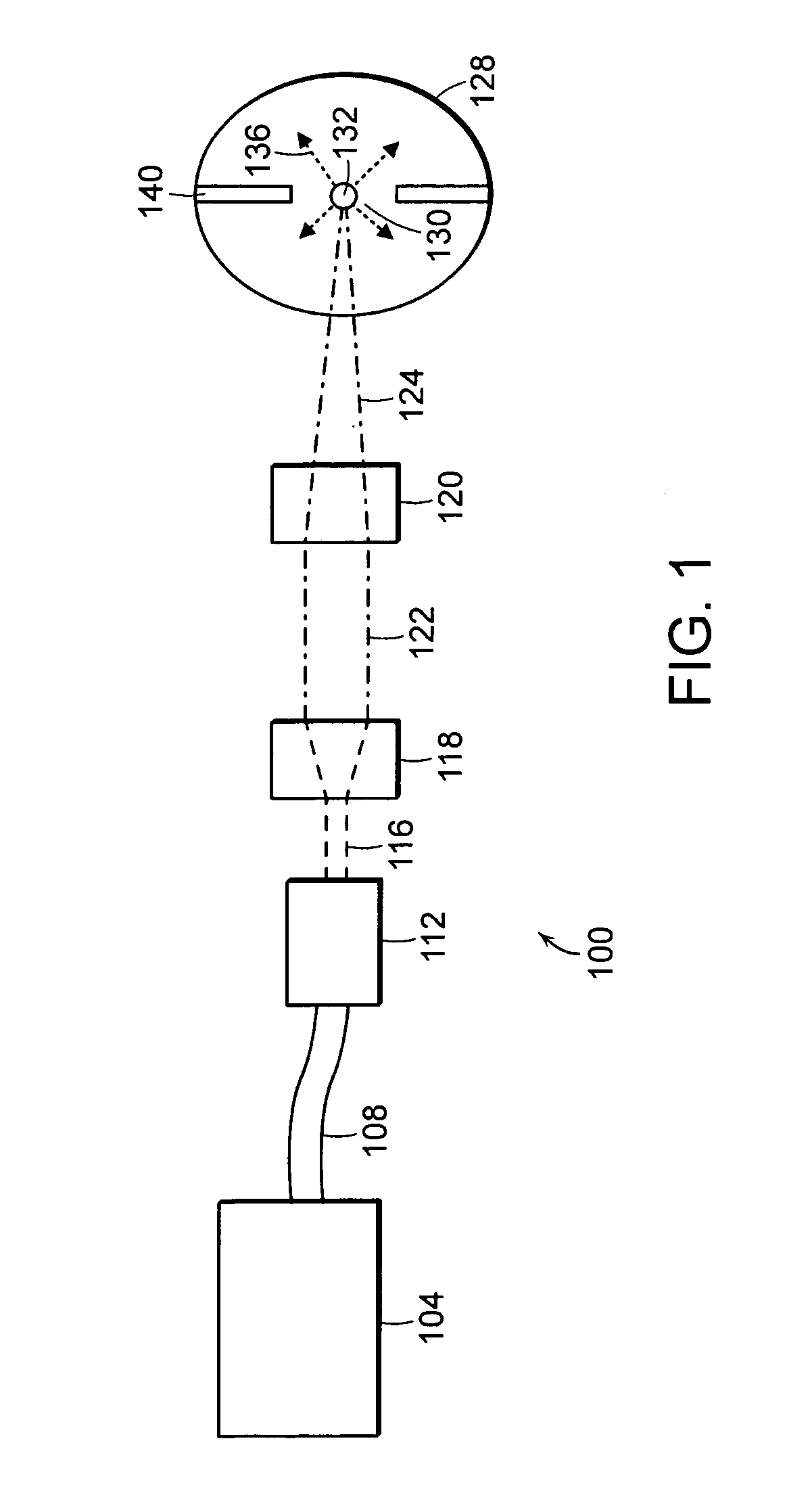
[0032]FIG. 1 is a schematic block diagram of a light source 100 for generating light, that embodies the invention. The light source 100 includes a chamber 128 that contains and ionizable medium (not shown). The light source 100 provides energy to a region 130 of the chamber 128 having the ionizable medium which creates a plasma 132. The plasma 132 generates and emits a high brightness light 136 that originates from the plasma 132. The light source 100 also includes at least one laser source 104 that generates a laser beam that is provided to the plasma 132 located in the chamber 128 to initiate and / or sustain the high brightness light 136.

[0033] In some embodiments, it is desirable for at least one wavelength of electromagnetic energy generated by the laser source 104 to be strongly absorbed by the ionizable medium in order to maximize the efficiency of the transfer of energy from the laser source 104 to the ionizable medium.

[0034] In some embodiments, it is desirable for the plas...


PUM


Abstract

An apparatus for producing light includes a chamber and an ignition source that ionizes a gas within the chamber. The apparatus also includes at least one laser that provides energy to the ionized gas within the chamber to produce a high brightness light. The laser can provide a substantially continuous amount of energy to the ionized gas to generate a substantially continuous high brightness light.

Description

FIELD OF THE INVENTION [0001] The invention relates to methods and apparatus for providing a laser-driven light source. BACKGROUND OF THE INVENTION [0002] High brightness light sources can be used in a variety of applications. For example, a high brightness light source can be used for inspection, testing or measuring properties associated with semiconductor wafers or materials used in the fabrication of wafers (e.g., reticles and photomasks). The electromagnetic energy produced by high brightness lights sources can, alternatively, be used as a source of illumination in a lithography system used in the fabrication of wafers, a microscopy systems, or a photoresist curing system. The parameters (e.g., wavelength, power level and brightness) of the light vary depending upon the application. [0003] The state of the art in, for example, wafer inspection systems involves the use of xenon or mercury arc lamps to produce light. The arc lamps include an anode and cathode that are used to exc...

Claims


Application Information

Patent Timeline
Patent Type & Authority Applications(United States)
IPC IPC(8): H01J27/24
CPCB82Y10/00G03F7/70033H05G2/001H01J61/54H01J65/042H01J61/025H01J65/04H01J61/02H05G2/008H05B41/382H05G2/003Y02B20/00
Inventor SMITH, DONALD K.
Owner HAMAMATSU PHOTONICS KK
Why Eureka
Try Eureka