Planar coupler and integrated antenna system

a technology of integrated antennas and couplers, which is applied in the structure of radiating elements, waveguide devices, resonance antennas, etc., can solve the problems that the electrical coupling between the balanced line and the unbalanced line cannot be produced insufficient degree, and achieve the reduction of manufacturing costs, insertion loss, and size and weight.

Inactive Publication Date: 2007-10-04
HATA HIROSHI +2
View PDF5 Cites 25 Cited by
  • Summary
  • Abstract
  • Description
  • Claims
  • Application Information

AI Technical Summary

Benefits of technology

[0017] In the present invention, a thin double-sided printed circuit board is essentially used (or additional one or more single sided boards are necessary for over three port circuit) as a substrate, whereby size and weight can be reduced. The balun or another such transformer or coupler is integrated with adjacent transmission line or transmission line elements, whereby a dramatic reduction in manufacturing costs can be achieved.
[0018] Insertion loss can be improved by dispensing with the use of ferrite cores used in conventional products, and by using a thin board having low RF loss. The bandwidth can be increased by making loops having a size and shape designed for the selected thin board, and layering the loops precisely. Accordingly, the transmission characteristics can be markedly improved.
[0019] Specifically, the effects achieved with the present invention are exhibited in a variety of transmission lines and adjacent elements that operate linearly in VHF, UHF, and SHF frequency ranges. In the microwave band, there are isolators, circulators, and other components that have traditionally employed the anisotropy of ferrite or the like. There are also many components that employ only the low loss and high permeability of ferrite, such as with RF transformers. So, the use of ferrite has been forced despite the fact that the latter preferably needs an inherently linear operation. Therefore, many components such as baluns, branching filters, and other couplers could not be operated in large-amplitude circumstances (in nonlinear operation), and have had a three-dimensional structure. However, with the recent emergence of thin high-quality RF boards, planar loops can be brought sufficiently close together, whereby satisfactory magnetic coupling M can be obtained without the use of ferrite. In addition, the thinness of the looped circuit board results in sufficient capacitance C at high frequencies. Therefore, by disposing the loops so as to constitute the equivalent circuit described later and shown in FIG. 4, a planar coupler became possible to have enough capacitive and inductive coupling.

Problems solved by technology

However, in a planar configuration in which an antenna and a balun are formed in the same plane, sufficient electrical coupling cannot be produced in the coupling between the balanced line and unbalanced line.

Method used


Image

  • Planar coupler and integrated antenna system
  • Planar coupler and integrated antenna system
  • Planar coupler and integrated antenna system

Examples


Embodiment Construction

[0049] The present invention shall be described below with reference to the drawings.

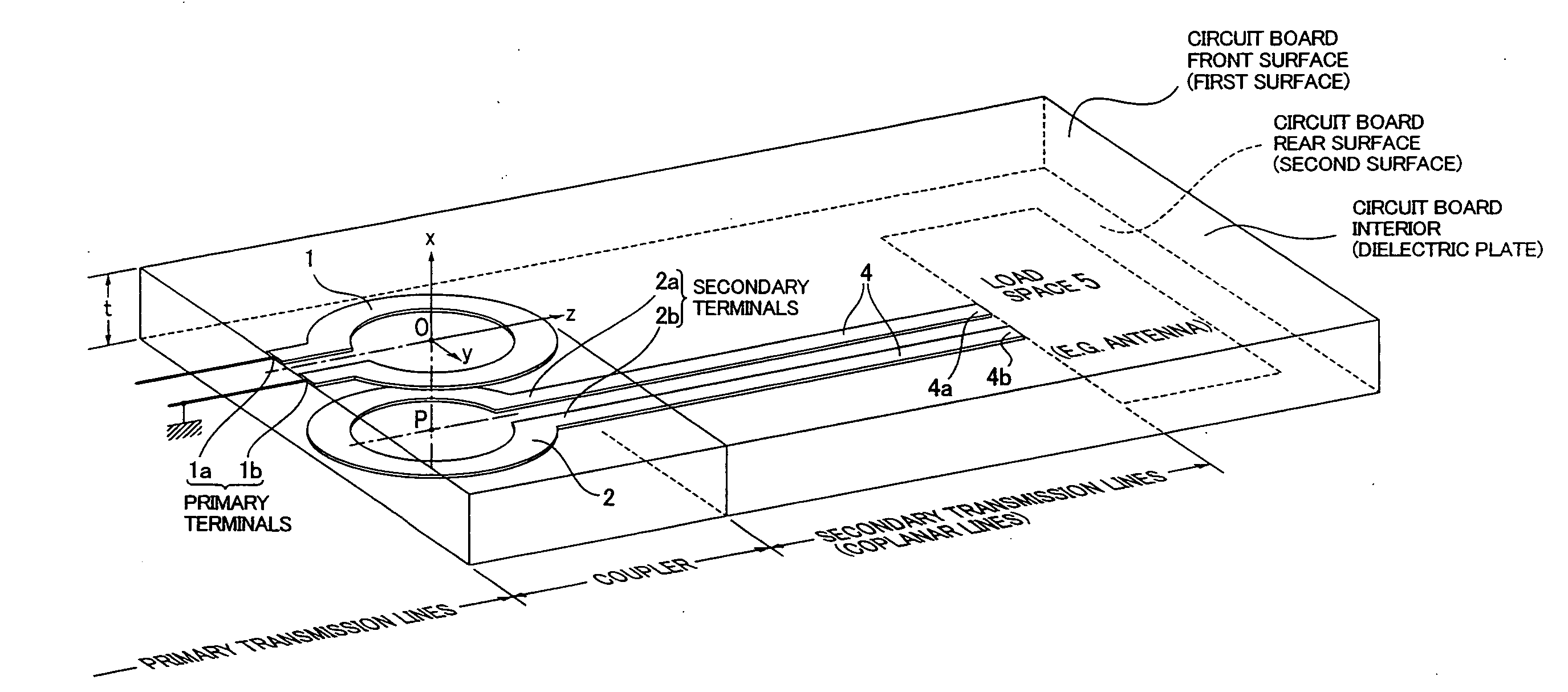
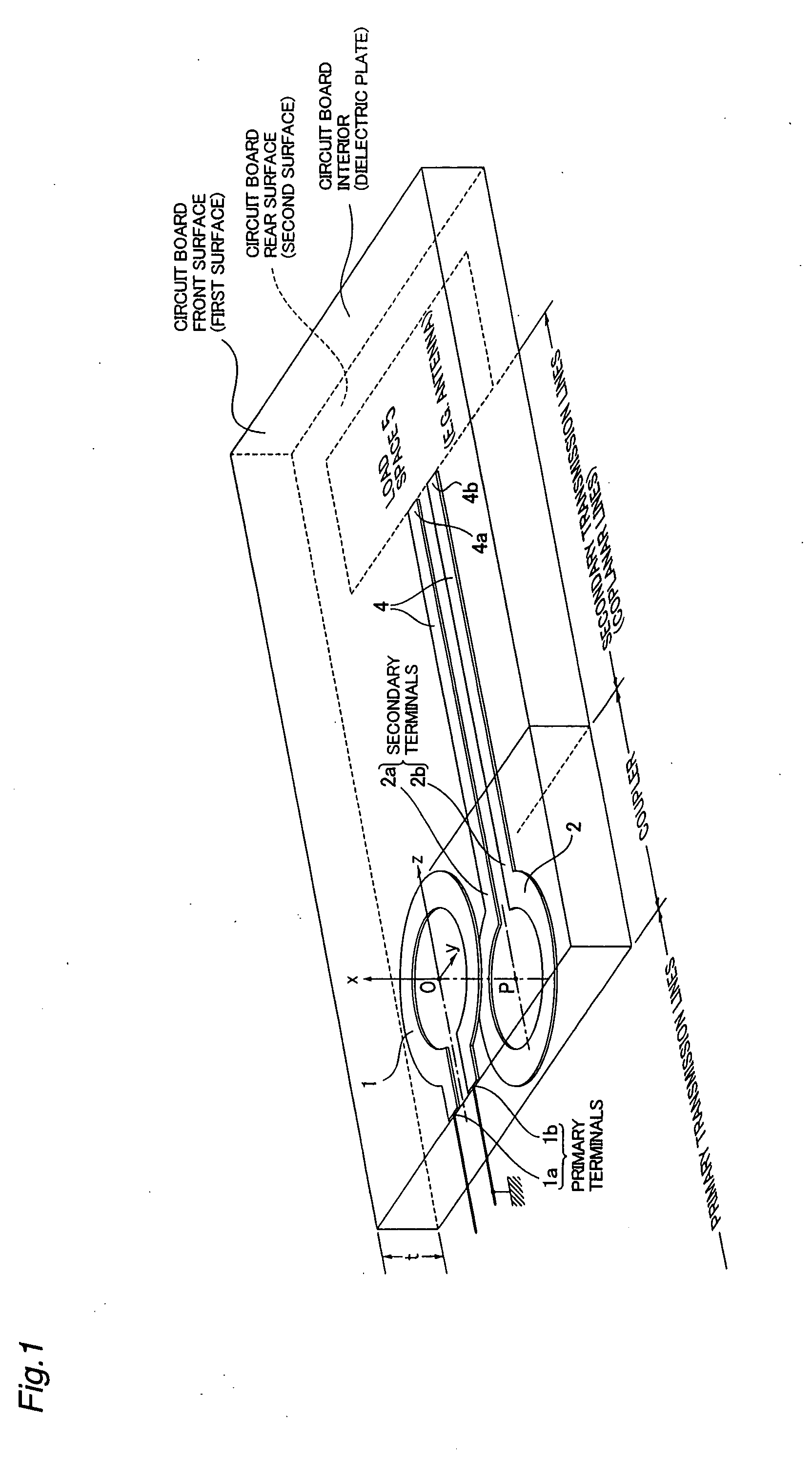
[0050] The following is a description, made with reference to FIG. 1, of the principle of the operation of the coupler, which is the basis of the present invention. In FIG. 1, circular loops 1, 2 having parts cut out (C-shaped primary loop and secondary loop patterns) are formed at the same positions but in opposite direction on the front and rear surfaces of a double-sided conductive foil printed circuit board (hereinafter referred to as double sided board). The circular loops 1, 2 thereby face each other across a dielectric plate (illustrated as being transparent for the sake of convenience in the description) having a thickness t. Terminals 1a, 1b of the cut portions of the loop 1 are primary loop terminals, and the same portions 2a, 2b of the loop 2 are secondary loop terminals, from which coplanar lines 4 extend in the Z direction up to terminals 4a, 4b. This configuration is an example of the...


PUM


Abstract

In a RF coupler that has high transmission efficiency in a broad range and that uses an RF printed layered circuit board, strong electrostatic coupling is obtained between circuits, and electromagnetic coupling is also used; C-shaped loops (1, 2) that have parts cut out face the surfaces of a dielectric plate having a thickness t; terminals (1a, 1b) connected to the two ends of the loop (1) are used as primary terminals; terminals (2a, 2b) of the loop (2) are used as secondary terminals; and coplanar lines (4) extend from these terminals along the surface of the dielectric plate up to terminals (41, 42). Therefore, the portions where the loops overlap are couplers, the coplanar lines are secondary transmission lines, and a wide variety of antennas not limited to dipoles may be connected to terminals (4a, 4b).

Description

CROSS-REFERENCE TO RELATED APPLICATIONS [0001] This application is a continuation-in-part of co-pending U.S. patent application Ser. No. 11 / 661,488, filed Feb. 27, 2007, which is incorporated herein in its entirety.TECHNICAL FIELD [0002] The present invention relates to a transformer or a coupler for coupling two or more high-frequency transmission circuits having different properties, and to an integrated antenna system. BACKGROUND ART [0003] Inputs and outputs of electronic circuits for handling high-frequency (RF) signals are often unbalanced transmission lines that are grounded on one side. Therefore, unbalanced coaxial lines or microstrip lines are used for transmission cables that are directly connected to terminals of the inputs and outputs. In contrast, dipole antennas, loop antennas, and other balanced antennas, which are essential elements, are often used. Therefore, a balun (one type of an RF transformer) is needed for such connections. [0004] In prior art, transformers i...

Claims


Application Information

Patent Timeline
Patent Type & Authority Applications(United States)
IPC IPC(8): H01Q1/38
CPCH01P5/10
Inventor HATA, HIROSHIKARAKAMA, TAKAHISA
Owner HATA HIROSHI
Why Eureka
Try Eureka