

Waste ink absorber and ink jet recording device incorporating the same
a waste ink absorber and ink jet technology, which is applied in the field of waste ink absorbers and ink jet recording devices, can solve the problems of reducing the efficiency of ink flushing and cleaning, etc., to achieve excellent ink absorption and retention properties, suppress foaming, and solve the effect of solvent resistan
- Summary
- Abstract
- Description
- Claims
- Application Information
AI Technical Summary
Benefits of technology
Problems solved by technology
Method used
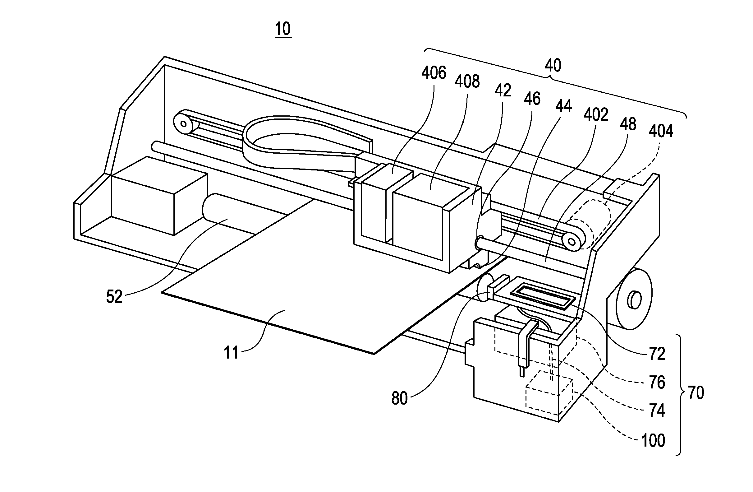
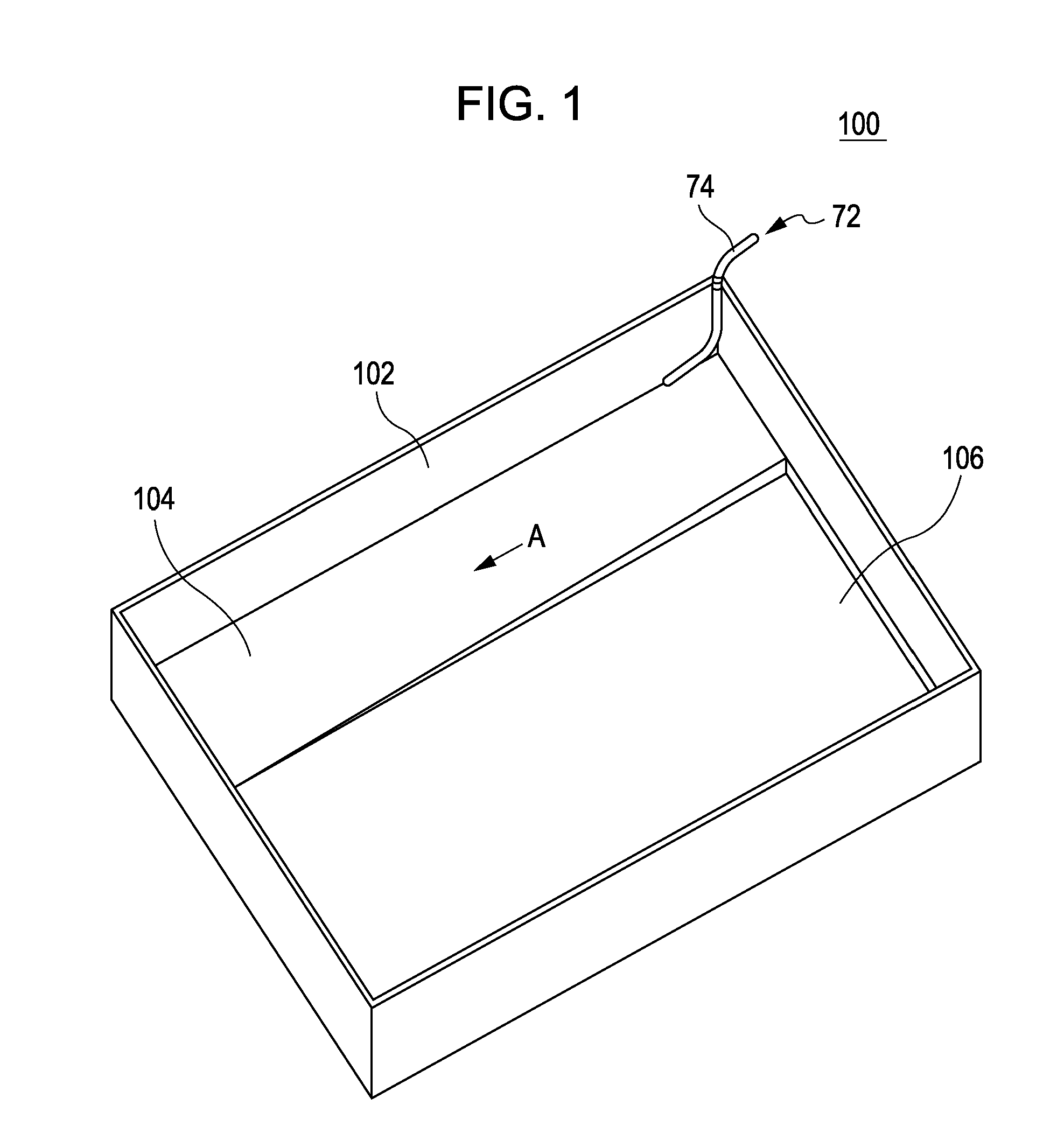
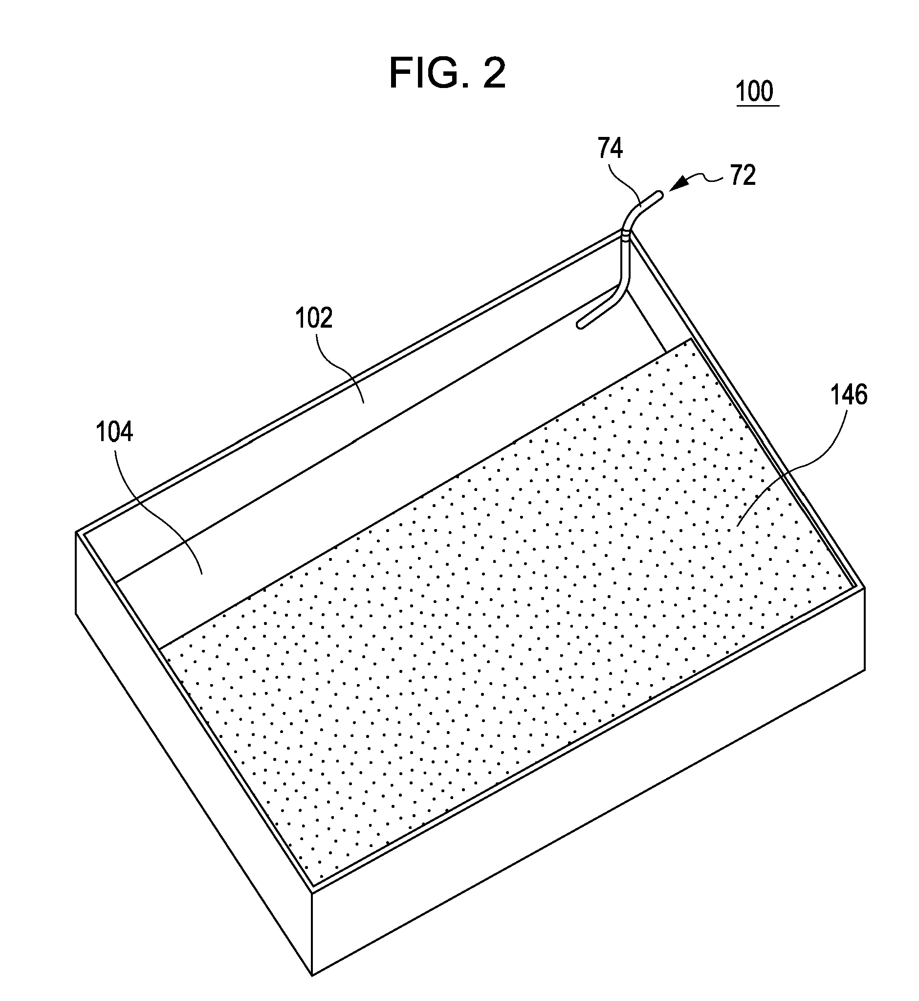
Image

Examples
example 1
Porous Material A
[0079]A ultragiant molecular weight-polyethylene having an average particle diameter of 160 μm and a melt flow rate (MFR) of 0.01 or less was filled in a gap portion of molding dies having rectangular cross-sections such that the layer thickness ratio is 70% of the total final thickness of the end product filter. The ultragiant molecular weight-polyethylene was then heated at 160° C. to 220° C. for 30 minutes to obtain a porous material (thickness: 20 mm) with a large pore diameter.
[0080]The porous material was homogeneously impregnated with an oily solvent, 3,5,5-trimethyl-1-hexanol (melting point: 70° C. or less, boiling point: 194° C.), such that the coating amount was 200 g / m2 to prepare a waste ink absorber A of Example 1.
example 2
Porous material B
[0081]A porous material having a pore diameter smaller than that of the porous material A of Example 1 above was obtained by the same method as in Example 1 except that an ultragiant molecular weight-polyethylene having an average particle diameter of 50 μm was used.
[0082]The porous material was homogeneously impregnated with an oily solvent, diethylene glycol diethyl ether (melting point: −44° C., boiling point 189° C.) such that the coating amount was 200 g / m2 to obtain a waste ink absorber B of Example 2.
example 3
Waste Ink Absorber C for Comparison
[0083]A soft polyurethane foam sheet having a thickness of 20 mm was used as the waste ink absorber for comparison. The sheet was homogeneously impregnated with diethylene glycol diethyl ether (melting point: −44° C., boiling point; 189° C.) such that the coating amount was 200 g / m2.
PUM
| Property | Measurement | Unit |
|---|---|---|
| boiling point | aaaaa | aaaaa |
| melting point | aaaaa | aaaaa |
| particle diameter | aaaaa | aaaaa |
Abstract
Description
Claims
Application Information