
Back Chassis Integrating Reflector, Back Light and Liquid Crystal Display

Inactive Publication Date: 2007-10-04
IDEMITSU KOSAN CO LTD
View PDF7 Cites 33 Cited by
  • Summary
  • Abstract
  • Description
  • Claims
  • Application Information

AI Technical Summary

Benefits of technology

[0032] An object of the present invention is to provide a reflector having a reduced number of components, a reduced number of assembly steps, and reduced weight and thickness, a backlight device using the same, and a liquid crystal display using the same.
[0034] A reflector provided with the chassis function having sufficient strength and rigidity for supporting a liquid crystal panel can be realized by integrating or laminating: a sheet metal back chassis in which a light source supporting section, a through-hole or groove for extracting a light source electrode terminal, a frame for supporting a light diffusing plate and a plurality of optical films, and a light diffusing plate support as required are integrally formed through sheet metal working and a light reflecting layer formed of a molded product of a light reflective thermoplastic resin material formed into a shape for covering the sheet metal back chassis. Thus, a backlight device and a liquid crystal display each having a reduced number of components, a reduced number of assembly steps, and reduced weight and thickness can be obtained.

Problems solved by technology

Thus, assembly of the backlight device requires double steps, and increase in weight of an entire device is inevitable.
In the light reflecting plate obtained by bonding and laminating a resin foam on an aluminum sheet metal substrate, a resin foamed layer is liable to peel off from the aluminum sheet metal substrate during sheet metal working and position shift may be caused.
Thus, sheet metal working of a complex shape involves difficulties.
However, an easily available and relatively inexpensive aluminum material of 52S cannot be used for imparting sheet metal working properties, and an expensive material must be used.
As described above, sheet metal working of a complex shape involves difficulties, and thus a reflector must be produced by: producing a light source support having a structure for preventing torsion and reinforcing a light reflecting plate and having functions of supporting a light source, supporting a reflecting section, insulating heat of a light source electrode terminal, and the like by using a resin composition by a separate injection molding method and attaching and fixing the light source support after the light source is provided to the light reflecting plate.
However, the sheet metal substrate is applied to the light reflecting plate alone, and no reflector having a structure provided with a back chassis and / or a light source support is proposed.
Meanwhile, in the case where a light reflecting plate is formed by using a polycarbonate-based thermoplastic resin composition containing titanium oxide and having a light reflecting function without using the aluminum substrate, suppression of warping and deformation caused by thermal expansion with temperature increase by heat from a light source involves difficulties.
Further, for formation of a chassis for supporting a liquid crystal panel as required, rigidity is hardly ensured (see Patent Documents 8 and 9, for example).

Method used


Image

  • Back Chassis Integrating Reflector, Back Light and Liquid Crystal Display
  • Back Chassis Integrating Reflector, Back Light and Liquid Crystal Display
  • Back Chassis Integrating Reflector, Back Light and Liquid Crystal Display

Examples


example 1

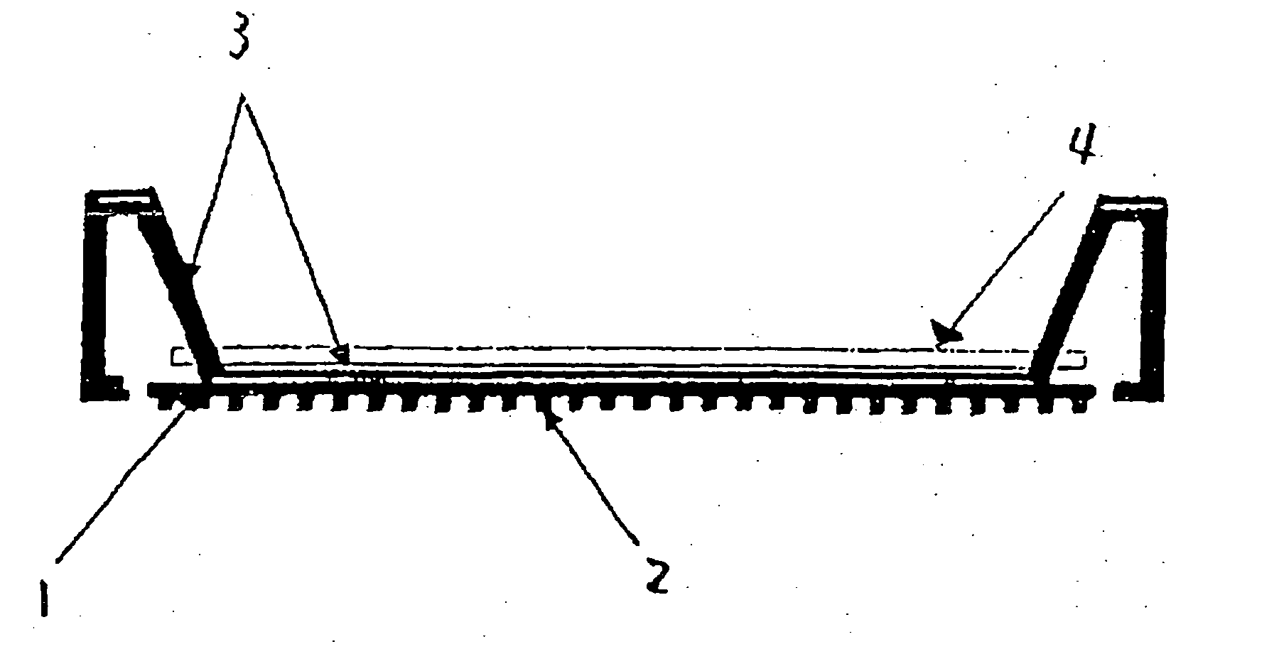
[0125] A back chassis (1) as shown in FIG. 1 having a reinforcing rib (2) on a back surface thereof, and having a light source supporting section, a through-hole for extracting a light source electrode terminal, and a frame (not shown) for supporting a light diffusing plate and a plurality of optical films integrally formed was produced through sheet metal working of an aluminum sheet metal.

[0126] Next, 79.4 mass % of a polycarbonate resin (FN1900A, available from Idemitsu Kosan Co., Ltd.), 20 mass % of titanium oxide (PC3, available from Ishihara Industry Co., Ltd.) as a white pigment, and 0.6 mass % of methyl hydrogen polysiloxane (SH1107, available from Dow Corning Toray Co., Ltd.) as a decomposition inhibitor were dry blended, and the obtained mixture was kneaded at a cylinder temperature of 280° C. by using a twin-screw extruder attached to vent (TEM-35, manufactured by Toshiba Machine Co., Ltd.), to thereby obtain pellets of a polycarbonate resin composition. The obtained pel...

example 2

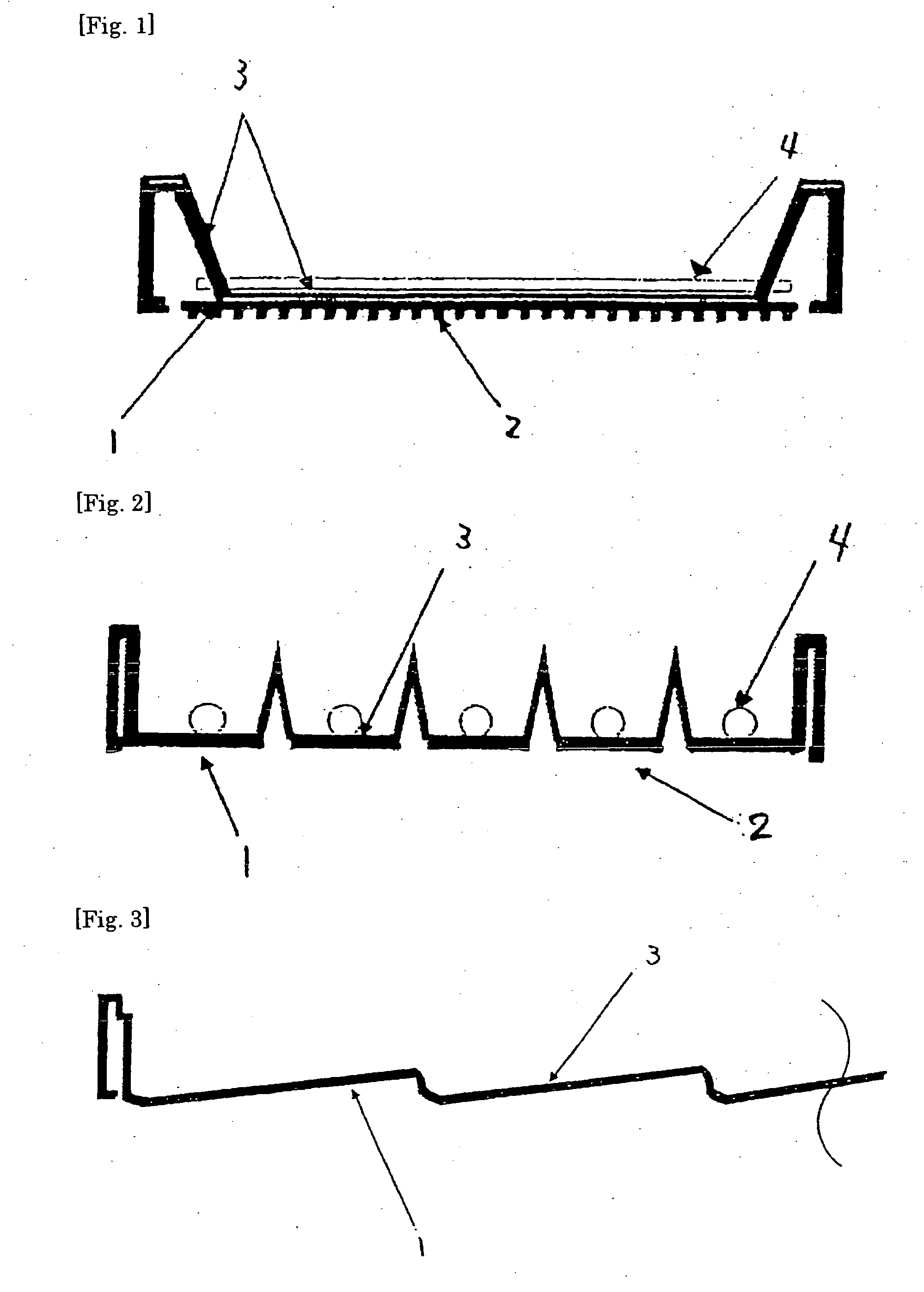
[0128] A reflector (b) as shown in FIG. 2 was produced in accordance with Example 1 except that: a back chassis as shown in FIG. 2 produced through sheet metal working of an aluminum sheet metal, having a reinforcing rib on a back surface, having a corrugated reflecting surface, and having a light source supporting section, a through-hole for extracting a light source electrode terminal, and a frame (not shown) for supporting a light diffusing plate and a plurality of optical films integrally formed was used; and pressure forming was conducted at a pressure of 588 kPaG. A direct type-backlight device was produced by using the obtained reflector (b) and arranging a light diffusing plate (5), light diffusing films (6), and a prism sheet (7) as shown in FIG. 5.

[0129] The number of components was reduced. As a result, not only reduction in weight and thickness of the backlight device and the liquid crystal display was realized, but also the numbers of production steps and assembly step...

example 3

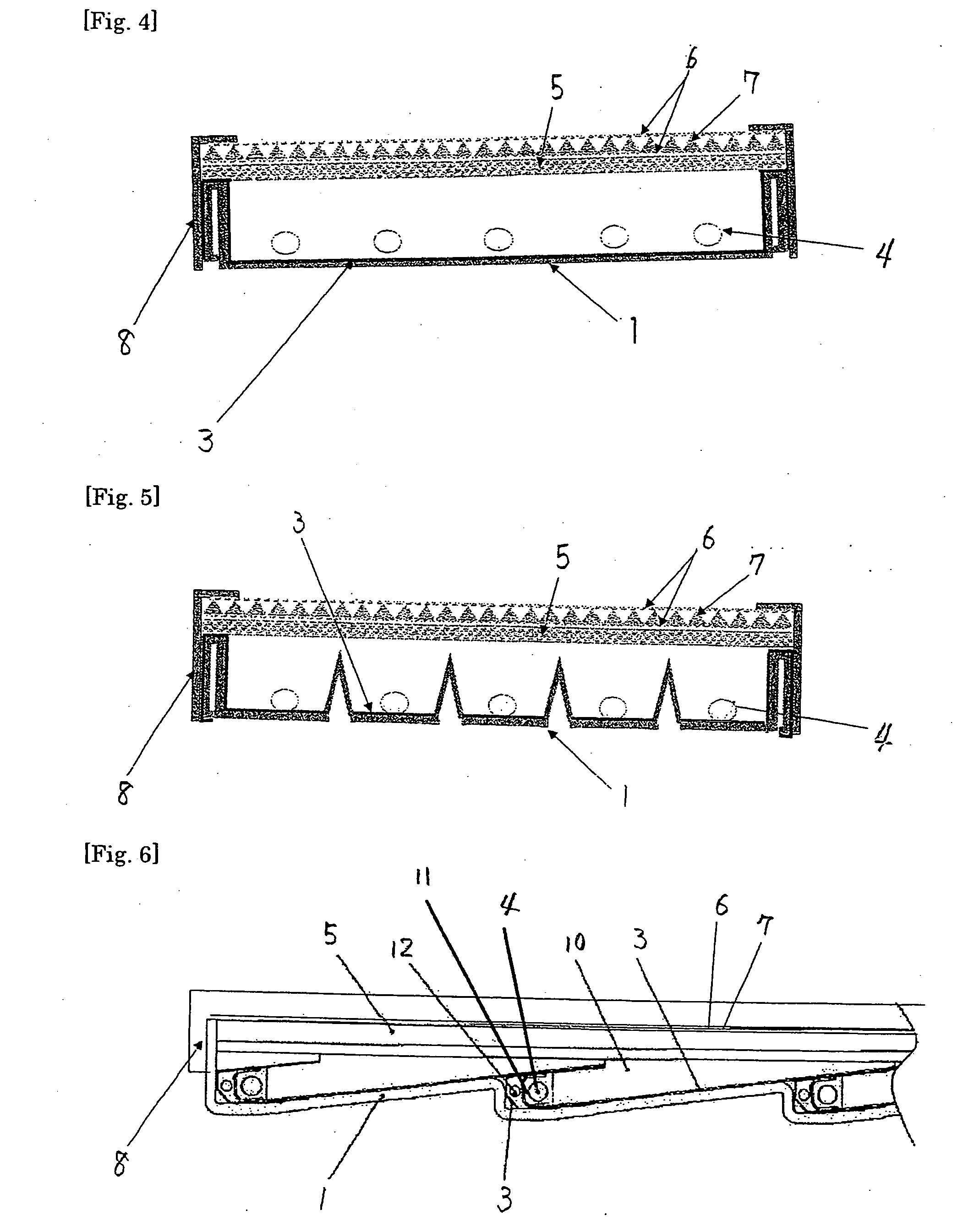
[0130] A reflector (c) as shown in FIG. 3 was produced in accordance with Example 1 except that a tandem-type back chassis as shown in FIG. 3 produced through sheet metal working of an aluminum sheet metal was used; and insert molding was conducted. A direct type tandem-type backlight device was produced by using the obtained reflector (c) and arranging a light guide plate (10), a light diffusing plate (5), light diffusing films (6), and a prism sheet (7) as shown in FIG. 6.

[0131] The light reflecting plate and the sheet metal back chassis were integrated or laminated, and the reflector does not need to be produced through separate sheet metal working by using a light reflecting plate formed by bonding and laminating a resin foam to an aluminum sheet metal substrate, and the number of components was reduced. Thus, reduction in weight and thickness of the backlight device and the liquid crystal display apparatus was realized, and the numbers of production steps and assembly steps we...


PUM


Abstract

A modularized reflector is produced by integrating or laminating: a sheet metal back chassis in which a light source supporting section, a through-hole or a groove for extracting a light source electrode terminal, and a frame for supporting a light diffusing plate and an optical film are integrally formed through sheet metal working; and a light reflecting layer made of a molded product of a light reflective thermoplastic resin material formed into a shape for covering the back chassis. By producing a backlight device and a liquid crystal display using the reflector, there are provided the reflector reduced in the number of components, in the number of assembly steps, and in weight and thickness, and a back light and a liquid crystal display using the reflector.

Description

TECHNICAL FIELD [0001] The present invention relates to a back chassis integrating reflector to be used for a backlight device or a liquid crystal display, to a backlight device using the same, and to a liquid crystal display using the same. BACKGROUND ART [0002] A liquid crystal display generally includes a backlight device and a liquid crystal panel. The backlight device is constructed of a sheet metal back chassis, a sheet metal front chassis, a light reflecting plate, a light source supporting section, a light source, a light diffusing plate, a light guide plate used as required, and a light source drive circuit such as an inverter. The liquid crystal display has a structure in which a liquid crystal panel is arranged and fixed on the backlight device. The backlight device is roughly classified into three types of a direct type, a light guide-type, and a tandem-type which is a hybrid of the two types. Of those, a backlight device to be used for a large screen liquid crystal TV r...

Claims


Application Information

Patent Timeline
IPC IPC(8): G02B5/08F21S2/00G02F1/13357
CPCG02B5/08G02F1/133604G02F2001/133628G02F1/133608G02F1/133605G02F1/133628
Inventor KAWATO, HIROSHIKOGURE, MASAMI
Owner IDEMITSU KOSAN CO LTD
Learn More