Current source inverter with energy clamp circuit and controlling method thereof having relatively better effectiveness

a current source inverter and clamp circuit technology, applied in the direction of dc-dc conversion, power conversion systems, instruments, etc., can solve the problems of harmonic wave interference, down the fuse, etc., and achieve the effect of reducing the voltage stress of a plurality of transistors and improving effectiveness

Inactive Publication Date: 2007-10-04
DELTA ELECTRONICS INC
View PDF2 Cites 15 Cited by
  • Summary
  • Abstract
  • Description
  • Claims
  • Application Information

AI Technical Summary

Benefits of technology

[0012]It is therefore an object of the present invention to provide a current source inverter with an energy clamp circuit and a controlling method thereof having a relatively better effectiveness such that when an AC output voltage of an utility power is disconnected with the current source inverter, the electrical power stored in an output inductor of the current source inverter would be discharged to an output capacitor and an input capacitor of the current source inverter via the energy clamp circuit so as to decrease the voltage stresses of a plurality of transistors of the current source inverter dramatically, and to avoid the inrush current when the utility power is connected with the current source inverter, a DC input voltage of the current source inverter is at one of the states being zero and being less than a peak value of the AC output voltage of the utility power.

Problems solved by technology

If the utility power (Utility) is connected to the current source inverter 2 of FIG. 3(a) when the DC input power supply V_in is not built up yet, a relatively large inrush current would be generated and flows through one of the diodes D_A and D_B, and the diodes D_C and D_D to the input capacitor C_in, the inrush current might burn down the fuse at the utility power (Utility) side, and would easily cause the interference of harmonic waves.

Method used


Image

  • Current source inverter with energy clamp circuit and controlling method thereof having relatively better effectiveness
  • Current source inverter with energy clamp circuit and controlling method thereof having relatively better effectiveness
  • Current source inverter with energy clamp circuit and controlling method thereof having relatively better effectiveness

Examples


Embodiment Construction

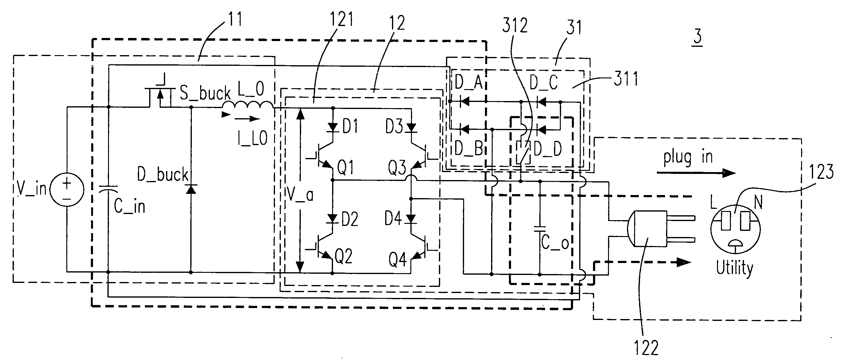
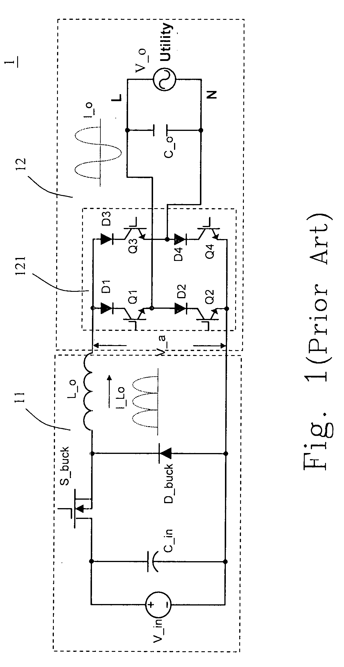
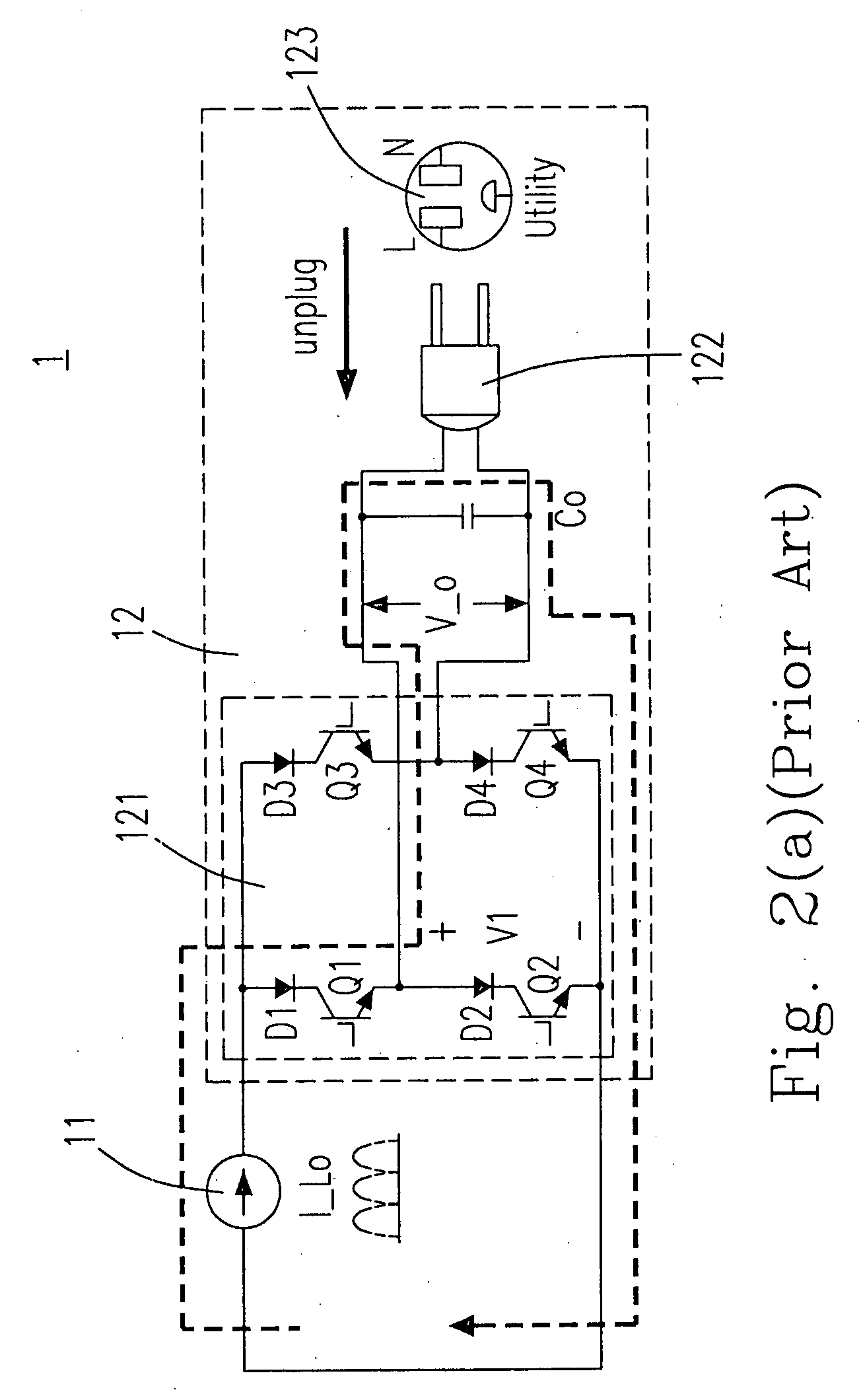
[0047]Please refer to FIG. 5(a), it shows a schematic circuit diagram of a current source inverter including an energy clamp circuit having a relatively better effectiveness according to the first preferred embodiment of the present invention and a potential inrush current route when the utility power is connected with the current source inverter, and the AC output voltage is at a positive half-cycle. In which, the current source inverter 3 includes the buck converter 11, the DC / AC converter 12 having the full bridge switching circuit 121, a plug 122 and a socket 123 (for providing the utility power), which are the same as those of FIGS. 3(a)-3(c), and an energy clamp circuit 31 having a plurality of diodes 311 (the first to the fourth diodes D_A, D_B, D_C and D_D, which are the same as those of 21 in FIG. 3(a)) and a switch 312.

[0048]The positive half-cycle inrush current route as shown in FIG. 5(a) is the same as the inrush current route of FIG. 4(a), which is employed to indicate...


PUM


Abstract

The provided current source inverter includes a buck converter having an input capacitor and an output inductor, receiving a DC input voltage, and generating an output inductor current, a DC/AC converter having an output capacitor, receiving the output inductor current and generating an AC output voltage, a load coupled to the DC/AC converter, and an energy clamp circuit coupled to the buck and the DC/AC converters. The energy clamp circuit includes a first diode and a second diode, provides a discharging route while the load is disconnected with the output capacitor such that the electrical power stored at the output inductor could be discharged to the output capacitor and the input capacitor and avoids an inrush current.

Description

FIELD OF THE INVENTION[0001]The present invention relates to a current source inverter and its controlling method. More particularly, the present invention relates to a current source inverter including an energy clamp circuit and its controlling method having a relatively better effectiveness.BACKGROUND OF THE INVENTION[0002]Please refer to FIG. 1, it is a schematic circuit diagram of a conventional current source inverter 1, which has a current source output I_o, and can be electrically connected to a utility power (Utility) in parallel. In FIG. 1, the current source inverter 1 includes a buck converter 11 and a DC / AC converter 12. The buck converter 11 includes an input capacitor C_in, a buck converter switch S_buck, a free-wheeling diode D_buck and a output inductor L_o receiving a DC input voltage V_in and generating an output inductor current I_Lo. The DC / AC converter 12 includes a full bridge switching circuit 121, which includes four unidirectional switches and an output cap...

Claims


Application Information

Patent Timeline
Patent Type & Authority Applications(United States)
IPC IPC(8): H02M3/335
CPCH02M1/32H02M2001/007H02M7/5387H02M1/36H02M1/007
Inventor CHAN, CHIH-CHIANGCHANG, YU-MING
Owner DELTA ELECTRONICS INC
Why Eureka
Try Eureka