
Current collector, negative electrode and battery

a negative electrode and current collector technology, applied in the field of current collectors, negative electrodes and batteries, can solve the problems of deterioration of the cycle characteristics of the battery, peeling (detachment strength decrease), and the active material layer of the negative electrode formed of a carbon material such as graphite may be difficult to greatly improve the properties, so as to achieve the effect of improving the durability of the battery and ensuring the effect of volume chang

Active Publication Date: 2007-10-04
MURATA MFG CO LTD
View PDF3 Cites 14 Cited by
  • Summary
  • Abstract
  • Description
  • Claims
  • Application Information

AI Technical Summary

Benefits of technology

[0016]According to an embodiment of the present invention, in the battery formed of the current collector and the negative electrode, occurrence of crack or fracture on the negative electrode may be controlled, and especially if the negative electrode active material layer is formed of the negative electrode active material that drastically changes its volume when charging and discharging the battery, durability against volume change may also be improved.
[0017]According to an embodiment of the present invention, since a current collector includes a first principal plane and a second principal plane having mutually different roughness between the first principal plane and the second principal plane, occurrence of crack or fracture on the electrode may be controlled.
[0018]Further, according to an embodiment of the present invention, since a negative electrode formed of a current collector includes a first principal plane and a second principal plane having mutually different roughness between the first principal plane and the second principal plane, occurrence of crack or fracture on the electrode may be controlled.
[0019]According to an embodiment of the present invention, since a battery includes a first principal plane and a second principal plane of the negative current collectors having mutually different roughness between the first principal plane and the second principal plane, higher capacity of the battery may be obtained by forming the battery using the negative electrode active material that drastically changes its volume while controlling occurrence of crack or fracture on the electrode.

Problems solved by technology

A battery including a negative electrode active material layer formed of a carbon material such as graphite may be difficult to greatly improve properties because a battery capacity of the negative electrode active material is about to reach the theoretical limit.
Increasing a thickness of an active material layer may improve battery capacity; however, if such thick electrode is formed of a smooth current collector typically used in the related art, peeling (detaching} strength decreases to deteriorate cycle characteristics of the battery.
Further, if an amount of a binder is increased so as to control to lower peeling strength, load characteristic of the battery is lowered, thereby adversely affecting the cycle characteristics of the battery.
However, if such a current collector includes rough surfaces for lowering peeling strength, the current collector may become susceptible to crack or fracture.
However, since the negative electrode active material containing silicon (Si) and tin (Sn) drastically changes its volume when charging and discharging the battery, the inner pressure increases to impose loads upon members located around the negative electrode active material.
Further, in an electrode having an alloyed interface between a current collector and an active material layer, both the current collector and the active material layer may be cracked or fractured, resulting in lowering the battery capacity.

Method used


Image

  • Current collector, negative electrode and battery
  • Current collector, negative electrode and battery
  • Current collector, negative electrode and battery

Examples


first embodiment

[0026]A current collector, a negative electrode, and a battery according to first embodiment of the present invention will be described below.

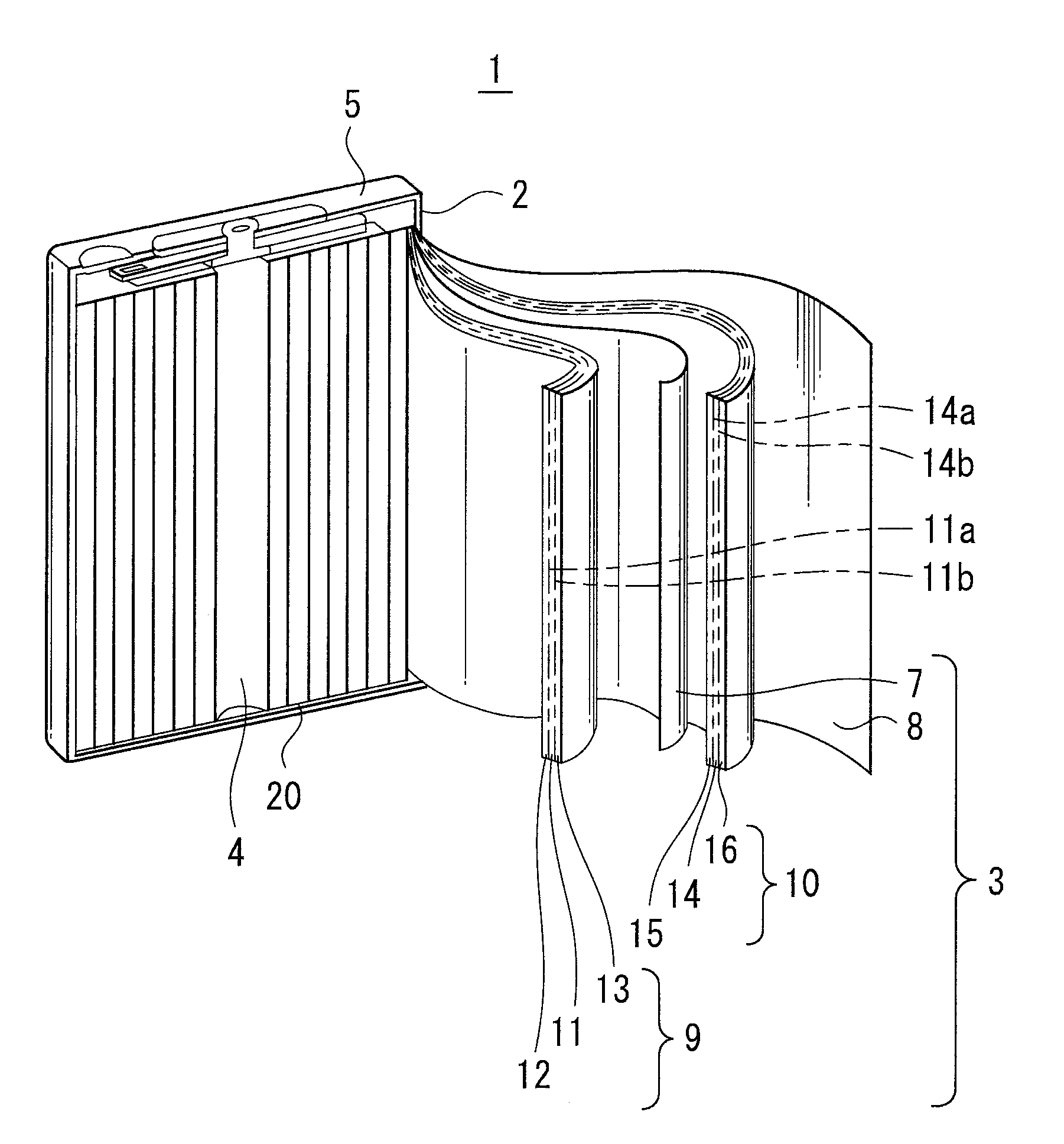
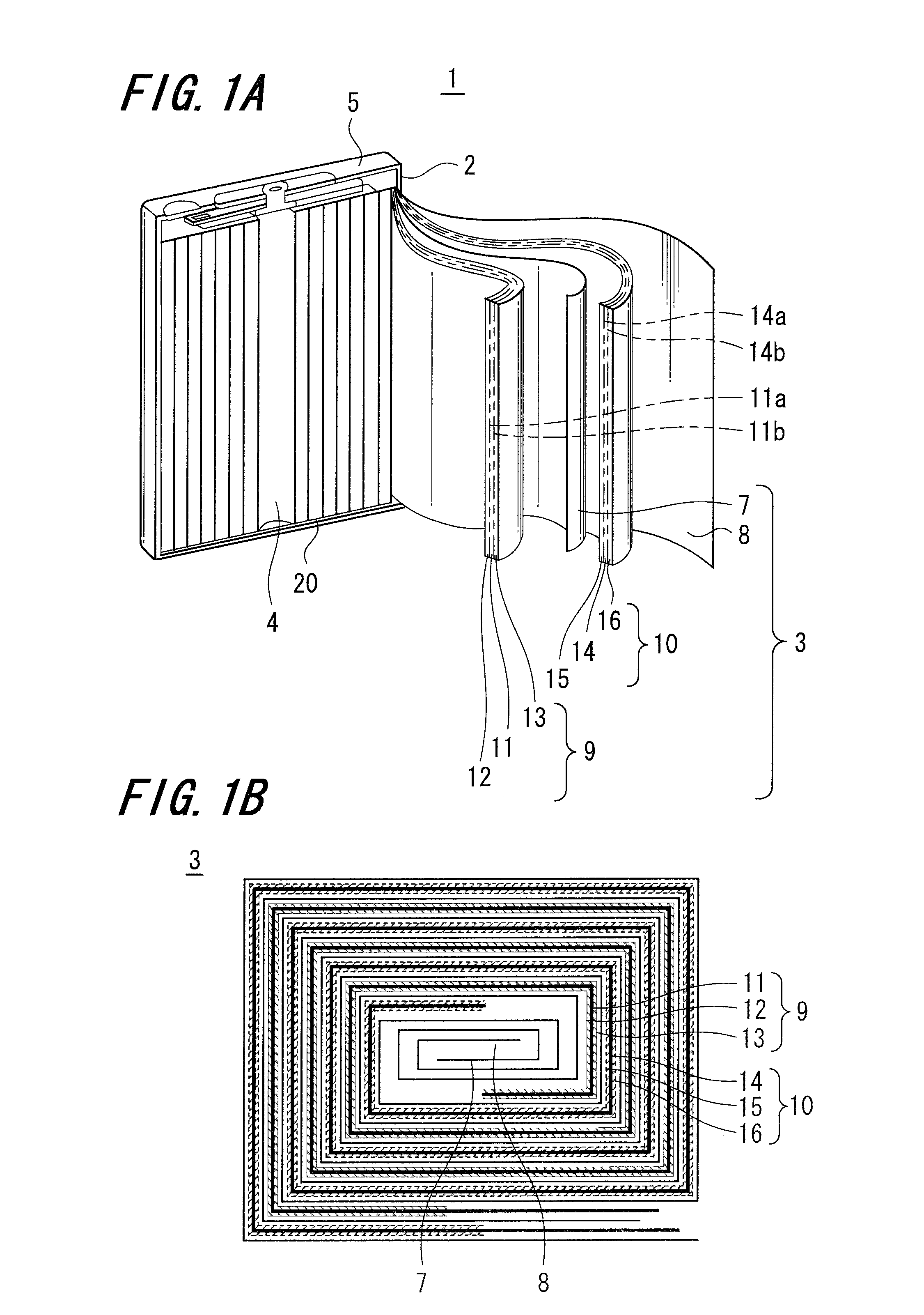
An element winding type rectangular battery will be described as shown in FIG. 1A illustrating a partially sectioned schematic perspective view according to an embodiment of the present invention.

[0027]As shown in FIG. 1A, a battery 1 according to the embodiment of the present invention includes an electrode winding body 3 located around a center 4 inside a prismatic battery can 2, an upper surface of which is opened and enclosed with a battery lid 5.

[0028]The battery can 2 is formed of a nickel-plated iron, and the electrode winding body 3 includes mutually faced wound positive and negative electrodes 9 and 10 through a pair of wound separators 7 and 8 containing electrolytes.

[0029]The battery lid 5 is attached to the battery can 2 by caulking through gaskets and the like. Specifically, the inside of the battery can 1 is air-tightly enclosed ...

second embodiment

[0062]A current collector, a negative electrode and a battery according to a second embodiment of the present invention will be described.

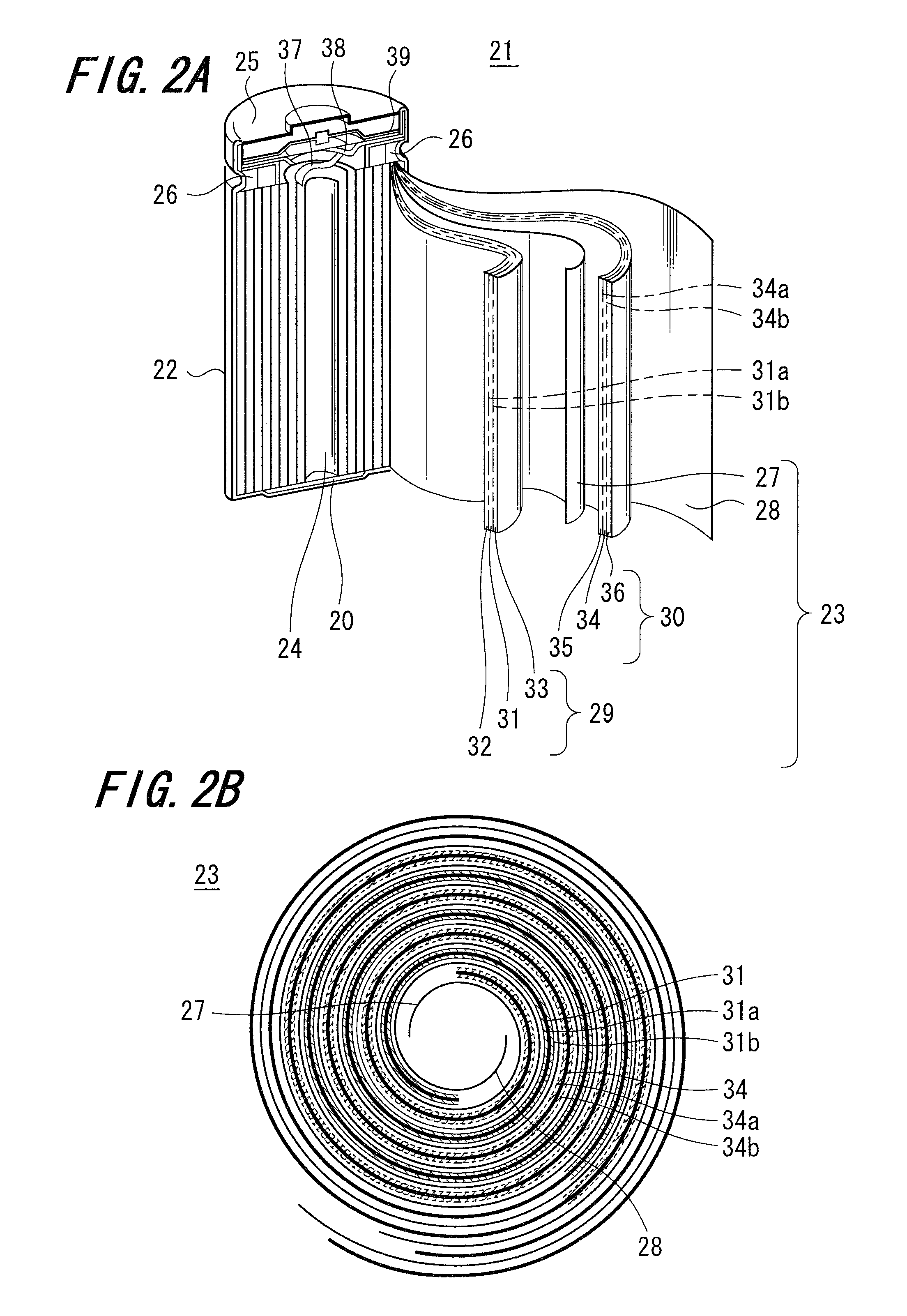
[0063]In this embodiment, a so-called element winding type cylindrical battery shown in a partly cutaway perspective view of FIG. 2A will be described.

[0064]As shown in FIG. 2A, a battery 21 according to the embodiment of the present invention includes a cylindrical battery can 22 with its upper surface opened in which a electrode winding body 23 is located at a center pin 24 (not shown) and which is sealed by a battery lid 25.

[0065]The battery can 22 is configured by a nickel-plated iron, and the electrode winding body 23 has an arrangement in which a positive electrode 29 and a negative electrode 30 similarly wound are located in an opposing fashion through a pair of wound separators 27 and 28 containing electrolyte.

[0066]The battery lid 25 includes a safety valve mechanism 38 together with a heat sensitive resistance element (positive temperatu...

third embodiment

[0103]A current collector, a negative electrode and a battery according to a third embodiment of the present invention will be described.

[0104]In this embodiment of the present invention, a battery of a type different from that of the first embodiment will be described with reference to an example of a so-called element bending system (stack system) rectangular battery shown in a partly cutaway perspective view of FIG. 3A.

[0105]A battery 41 according to the embodiment of the present invention has an arrangement in which a bending body 43a is located within a prismatic battery can 42 of which upper surface is opened and the battery can 42 is sealed by a battery lid 55.

[0106]The battery can 42 is made of a nickel-plated iron, for example, and the bending body 43a has an arrangement in which positive and negative electrodes 29 and 30 bent in a like manner are located in an opposing fashion through a pair of separators 47 and 48 bent containing an electrolyte. It should be noted that th...


PUM

PropertyMeasurementUnit
arithmetic mean roughnessaaaaaaaaaa
thicknessaaaaaaaaaa
volume changeaaaaaaaaaa

Abstract

A current collector includes a first principal plane and a second principal plane. In the current collector, the roughness of the first principal plane and second principal plane being mutually different.

Description

CROSS REFERENCES TO RELATED APPLICATIONS[0001]The present invention contains subject matter related to Japanese Patent Application JP 2006-095608 filed in the Japanese Patent Office on Mar. 30, 2006, the entire contents of which being incorporated herein by reference.BACKGROUND OF THE INVENTION[0002]1. Field of the Invention[0003]The present invention relates to a battery including a positive electrode, a negative electrode, an electrolyte, and a negative electrode current collector, at least part of which is formed as a rough surface, and also relates to a current collector and a negative electrode forming the battery.[0004]2. Description of the Related Art[0005]With progress in science and technology such as semiconductor technology, personal computers (PCs), mobile phones, and the like have been developed, and batteries utilized as power supply for electronic apparatus have been expected to facilitate handling of the batteries such as reduction in size and weight, and to exhibit ...

Claims


Application Information

Patent Timeline
Patent Type & Authority Applications(United States)
IPC IPC(8): H01M4/64H01M4/58H01M4/02H01M4/13H01M4/134H01M4/38H01M4/70H01M10/05H01M10/0587
CPCH01M4/134H01M4/382H01M4/587H01M4/661Y02E60/122H01M4/745H01M10/0583H01M10/0587H01M2004/027H01M4/70H01M4/38H01M4/386H01M4/387Y02E60/10Y02P70/50H01M4/02H01M4/64H01M10/02H01M4/364H01M4/485H01M4/505H01M4/525H01M4/583H01M10/0431H01M10/0525H01M10/0568H01M10/0569H01M2220/30H01M2300/0028
Inventor KAWASE, KENICHIKONISHIIKE, ISAMUTAKADA, TOMOOIWAMA, MASAYUKIMORITA, NOZOMUKATO, YOSHIKAZU
Owner MURATA MFG CO LTD
Learn More