
Piezoelectric vibrator

a technology of piezoelectric vibrators and conductive films, which is applied in the direction of piezoelectric/electrostrictive/magnetostrictive devices, mechanical vibration separation, piezoelectric/electrostrictive/magnetostrictive machines, etc., can solve the problem of production yields, limiting the miniaturization of ultrasonic vibrators, and reducing the reliability of products. , the effect of low cost and simple structur

Active Publication Date: 2007-10-11
SAMSUNG ELECTRO MECHANICS CO LTD
View PDF7 Cites 19 Cited by
  • Summary
  • Abstract
  • Description
  • Claims
  • Application Information

AI Technical Summary

Benefits of technology

[0013]An advantage of the present invention is that it provides a small-sized piezoelectric vibrator that can provide high efficiency and be manufactured at low cost by using a simpler structure with a least side electrode and without an additional conductive film.
[0014]Another advantage of the present invention is that it provides a piezoelectric vibrator that can cope with various vibration frequency variations for mass production by soldering the wire in order to apply the AC voltage to the nodal point of the piezoelectric vibrator and can further improve the reliability of the piezoelectric vibrator.
[0015]A further advantage of the present invention is that it provides a method for manufacturing a piezoelectric vibrator, which can be manufactured in small size at low cost and can be mass-produced.
[0016]Additional aspect and advantages of the present general inventive concept will be set forth in part in the description which follows and, in part, will be obvious from the description, or may be learned by practice of the general inventive concept.
[0017]According to an aspect of the invention, a piezoelectric vibrator includes: a piezoelectric element including a first piezoelectric element layer having a bisected top electrode formed thereon, a second piezoelectric element provided under the first piezoelectric element layer and having an internal ground electrode formed thereon, and a third piezoelectric element provided under the second piezoelectric element layer, the third piezoelectric element having an internal electrode symmetrical with the top electrode with respect to a stack plane, and a bottom electrode formed in a plane opposite to the plane where the internal electrode is formed; a side electrode including first and second side electrodes for electrically connecting electrode patterns formed in a diagonal direction among the electrode patterns formed in the first and third piezoelectric element layers of the piezoelectric element, and a third side electrode for electrically connecting the internal ground electrode of the second piezoelectric element layer to the bottom electrode of the third piezoelectric element layer; and a power transmission member formed in one side of the piezoelectric element to transmit vibration generated from the piezoelectric element to the outside.
[0018]According to another aspect of the present invention, a piezoelectric vibrator includes: a piezoelectric element including an N-layer stacked structure including a plurality of first piezoelectric element layers where bisected top electrodes are formed and a plurality of second piezoelectric element layers where internal ground electrodes are formed, the first piezoelectric element layers and the second piezoelectric element layers being alternately stacked in sequence, and an M-layer stacked structure provided under the N-layer stacked structure, the M-layer stacked structure having a plurality of third piezoelectric element layers where internal electrodes are formed symmetrical with the top electrodes of the first piezoelectric element of the N-layer stacked structure with respect to a stack plane, and a plurality of second piezoelectric element layer stacked on the N-layer stacked structure, the third piezoelectric element layers and the second piezoelectric element layers being alternately stacked downward in sequence, the third piezoelectric element layer being disposed at the lowermost of the M-layer stacked structure; a side electrode including first and second side electrodes for electrically connecting electrode patterns disposed in a diagonal direction among the electrode patterns formed in the N-layer and M-layer stacked structures of the piezoelectric element, and a third side electrode for electrically connecting the internal ground electrodes of the N-layer and M-layer stacked structures and the bottom electrode of the M-layer stacked structure; and a power transmission member formed in one side of the piezoelectric element to transmit vibration generated from the piezoelectric element to the outside.

Problems solved by technology

Therefore, there is a limitation in miniaturization of the ultrasonic vibrator.
In addition, there is a problem in miniaturization because a plurality of side electrodes used for the external electrode are formed.
Due to the size characteristic of the external electrode, it is practically difficult to form the conductive films on the surface of the vibrator so as to electrically connect the external electrodes of the first external electrode group to the external electrodes of the second external electrode group.
An electric short degrades the reliability of product and the production yield.
A problem of the related art including U.S. Pat. No. 6,720,711, U.S. Patent Publication No. 2004 / 0189155, and Japanese Laid-open Patent Publication No. 2004-297951 is to secure a wire connection in a piezoelectric vibrator body.
As the size of the vibrator is decreasing, an electric wiring becomes an important issue.
Based on this fact, in the case of a small-sized vibrator where a solder dot is not placed at a nodal point (a position that does not move during vibration), the high acceleration weakens a solder strength, causing a serious problem in operation of the piezoelectric vibrator.

Method used


Image

  • Piezoelectric vibrator
  • Piezoelectric vibrator
  • Piezoelectric vibrator

Examples


embodiment 1

[0095]FIG. 9 is a perspective view of a piezoelectric vibrator according to a first embodiment of the present invention, and FIG. 10 is an exploded perspective view of the piezoelectric vibrator shown in FIG. 9.

[0096]The piezoelectric vibrator includes a piezoelectric element having four vibration parts, an internal electrode pattern, an external electrode pattern, and a power transmission member.

[0097]As shown in FIGS. 9 and 10, the piezoelectric element 400 includes an N-layer stacked structure 410 and an M-layer stacked structure 420. The N-layer stacked structure 410 is provide by alternately stacking a first piezoelectric element layer 110 and a second piezoelectric element layer 120. The M-layer stacked structure 420 is provided under the N-layer stacked structure 410 by alternately stacking a third piezoelectric element layer 130 and the second piezoelectric element layer 120.

[0098]Top electrodes 111 and 112 divided by two regions are formed on the first piezoelectric element...

embodiment 2

[0120]FIG. 13 is a perspective view of a piezoelectric vibrator according to a second embodiment of the present invention, and FIG. 14 is an exploded perspective view of the sheet (the piezoelectric sheet 620 of FIG. 11B) for the internal ground electrode, the third piezoelectric sheet 630 for the internal electrode, the second piezoelectric sheet 620 for the internal ground electrode, piezoelectric vibrator shown in FIG. 13.

[0121]Since the piezoelectric vibrator of FIG. 13 is almost similar to the piezoelectric vibrator according to the first embodiment of the present invention, the following description will be focused on different components.

[0122]Unlike the first embodiment, portions of the internal ground electrode 121 and the bottom electrode 133 extend up to the outside of both sides of the piezoelectric element. Therefore, the third side electrode 230 electrically connecting the N-layer and M-layer internal ground electrodes 121 and the bottom electrode 133 is formed on the ...

embodiment 3

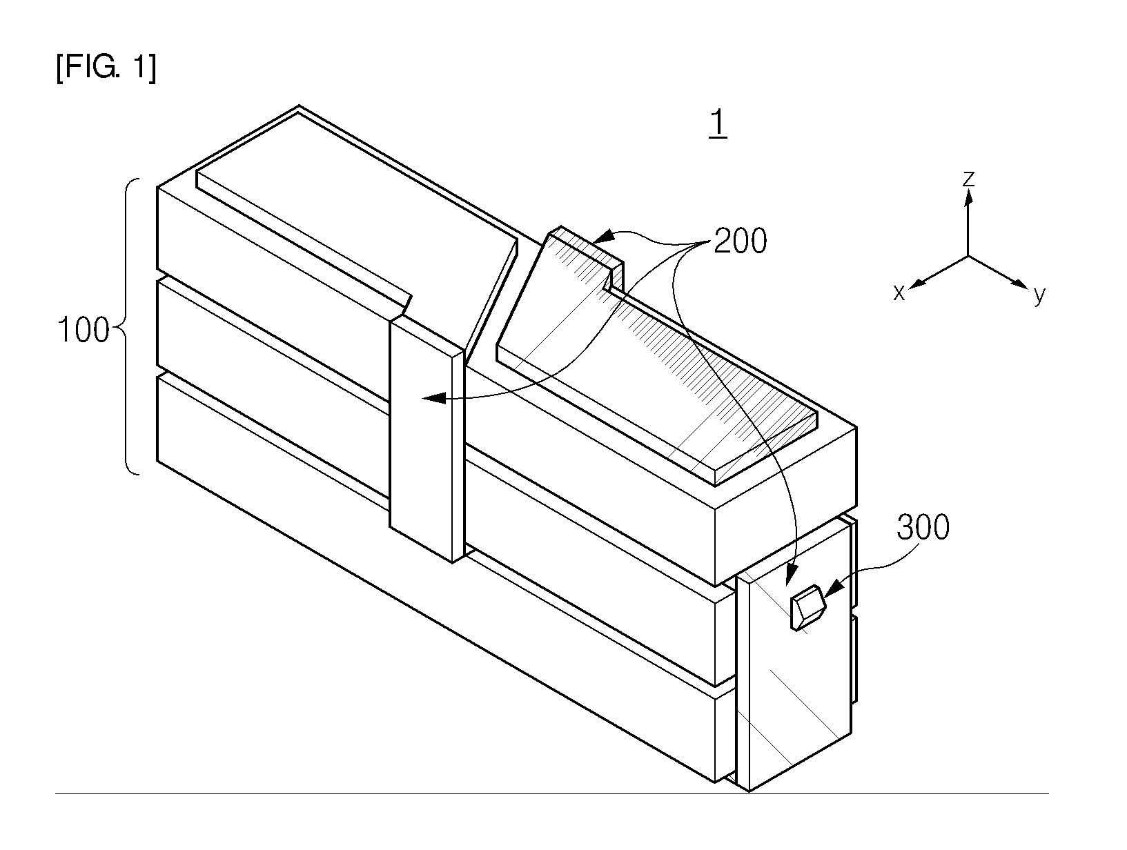
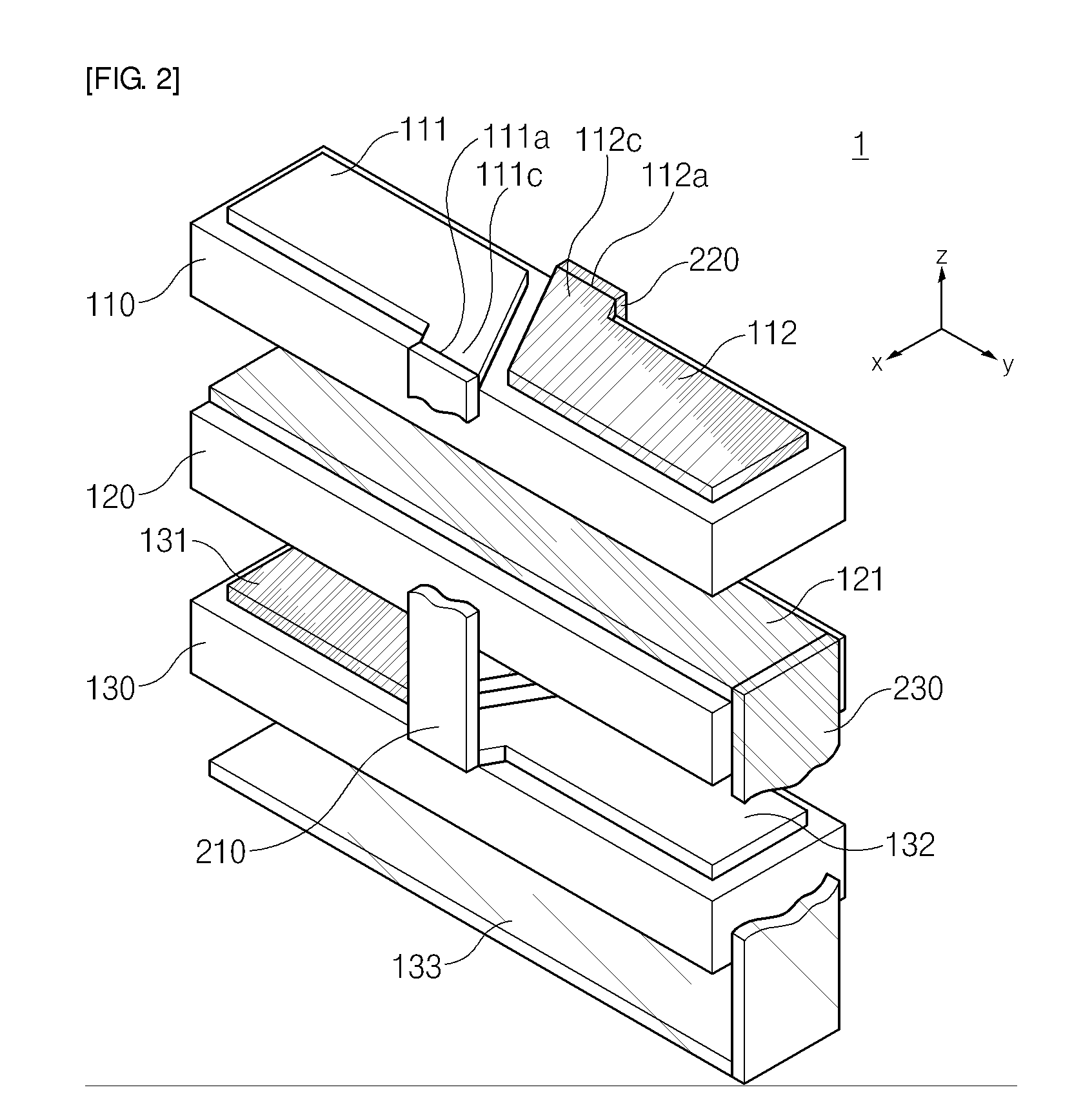
[0126]FIG. 16 is a perspective view of a piezoelectric vibrator according to a third embodiment of the present invention, and FIG. 17 is an exploded perspective view of the piezoelectric vibrator shown in FIG. 16.

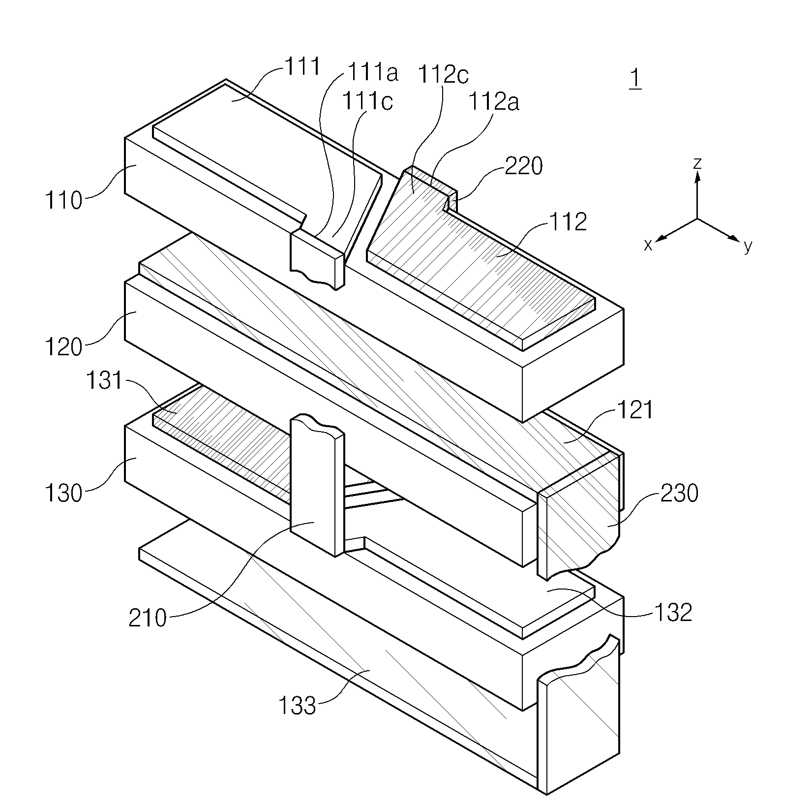
[0127]Since the piezoelectric vibrator of FIG. 16 is almost similar to the piezoelectric vibrator according to the first embodiment of the present invention, the following description will be focused on different components, including the bent portions of the electrodes.

[0128]Top electrode and internal electrodes 111 and 112 formed in an N-layer stacked structure 410 and M-layer internal electrodes 131 and 132 having a shape symmetrical with them have bent patterns 111c, 112c, 131c and 132c such that one ends 111a and 112a adjacent to one another among the bisected patterns extend up to the edge of the piezoelectric element in an opposite direction from the center of the piezoelectric element.

[0129]Unlike the first embodiment, the bent patterns of the top electrode 111 and ...


PUM


Abstract

Provided is a piezoelectric vibrator that can finely drive a device by generating an elliptical motion using a combination of a longitudinal vibration and a flexural vibration. The piezoelectric vibrator can also provide high efficiency and be manufactured at low cost by using a simpler structure. The piezoelectric vibrator includes a piezoelectric element, first to third side electrodes, and a power transmission member. The piezoelectric element includes: a first piezoelectric element layer having a bisected top electrode formed thereon; a second piezoelectric element provided under the first piezoelectric element layer and having an internal ground electrode formed thereon; and a third piezoelectric element provided under the second piezoelectric element layer, the third piezoelectric element having an internal electrode symmetrical with the top electrode with respect to a stack plane, and a bottom electrode formed in a plane opposite to the plane where the internal electrode is formed. The first and second side electrodes electrically connect electrode patterns formed in a diagonal direction among the electrode patterns formed in the first and third piezoelectric element layers of the piezoelectric element, and the third side electrode electrically connects the internal ground electrode of the second piezoelectric element layer to the bottom electrode of the third piezoelectric element layer. The power transmission member is formed in one side of the piezoelectric element to transmit vibration generated from the piezoelectric element to the outside.

Description

CROSS-REFERENCE TO RELATED APPLICATIONS[0001]This application claims the benefit of Korean Patent Application No. 10-2006-0031621 filed with the Korea Intellectual Property Office on Apr. 6, 2006, the disclosure of which is incorporated herein by reference.BACKGROUND OF THE INVENTION[0002]1. Field of the Invention[0003]The present invention relates to a piezoelectric vibrator, and more particularly, to a piezoelectric vibrator that can finely drive a device within a small limited space such as a portable electronic device by generating an elliptical motion using a combination of a longitudinal vibration and a flexural vibration.[0004]2. Description of the Related Art[0005]In recent years, an ultrasonic motor using a piezoelectric vibrator is considered as a new motor replacing an electromagnetic motor. Compared with the electromagnetic motor, the ultrasonic motor using the piezoelectric vibrator has an excellent resolution and a reduced noise and generates no magnetic field.[0006]A ...

Claims


Application Information

Patent Timeline
IPC IPC(8): H01L41/00H01L41/083B06B1/06H02N2/00
CPCH01L41/047H01L41/083H01L41/0472H02N2/004H02N2/026H01L41/0913H10N30/872H10N30/871H10N30/2023H10N30/50H10N30/87H10N30/80H10N30/20
Inventor KOC, BURHANETTINLEE, DONG KYUNRYU, JUNG HOKANG, BYUNG WOO
Owner SAMSUNG ELECTRO MECHANICS CO LTD
Learn More