Optical Displacement Sensor Comprising a Wavelength-tunable Optical Source

a technology of optical displacement sensor and wavelength-tunable optical source, which is applied in the field of displacement sensor, can solve the problems of increasing the resonant frequency, affecting the interferometer response, increasing the cost and complexity of the microphone, etc., and achieves the effect of overcompensating the impairment of signal transmission

Inactive Publication Date: 2007-10-11
SYMPHONY ACOUSTICS
View PDF18 Cites 90 Cited by
  • Summary
  • Abstract
  • Description
  • Claims
  • Application Information

AI Technical Summary

Benefits of technology

[0013] Embodiments of the present invention derive any one or more of the following advantages over the prior art by applying control in the optical domain to “match” the operating wavelength and resonant cavity:
[0016] 3) a simpler control system (control of the operating wavelength is easier to implement than precise mechanical control of the initial cavity length);
[0018] 5) a longer initial cavity length, and therefore a reduction of undesirable dynamic effects; and
[0019] 6) an ability to use signal modulation techniques to overcome signal transmission impairments.

Problems solved by technology

The use of an electrostatic actuator to tune L0 has three main drawbacks: 1) deforming the membrane increases its internal stress, thereby increasing its resonant frequency and affecting interferometer response; 2) a high electric-field is required to generate sufficient force to deflect the membrane; and 3) the addition of an electrostatic actuator complicates the fabrication of the Fabry-Perot interferometer, which increases the cost and complexity of the microphone.
The use of a high voltage is undesirable in most applications, since it requires high-power electronics and / or charge pumps.
High-power electronics are known to have poor reliability as compared to that of low-power electronics.
Also, the quiescent power dissipation of high-power electronics leads to significant power consumption; this is particularly undesirable in applications such as hearing aids and cell phones.
Finally, the use of a high-voltage actuator creates a potential safety hazard, which is particularly undesirable in the case of hearing aid microphones.
A short cavity length, however, results in undesirable dynamic effects that negatively impact Fabry-Perot interferometer performance, such as the well-known “squeeze-film” effect.
This results in generation of “noise pressure,” which contributes directly to the noise in the output signal, thereby degrading SNR.

Method used


Image

  • Optical Displacement Sensor Comprising a Wavelength-tunable Optical Source
  • Optical Displacement Sensor Comprising a Wavelength-tunable Optical Source
  • Optical Displacement Sensor Comprising a Wavelength-tunable Optical Source

Examples


Embodiment Construction

[0033] Some embodiments of the present invention incorporate subject matter disclosed in U.S. patent application Ser. No. 11 / 366,730, which is incorporated by reference herein.

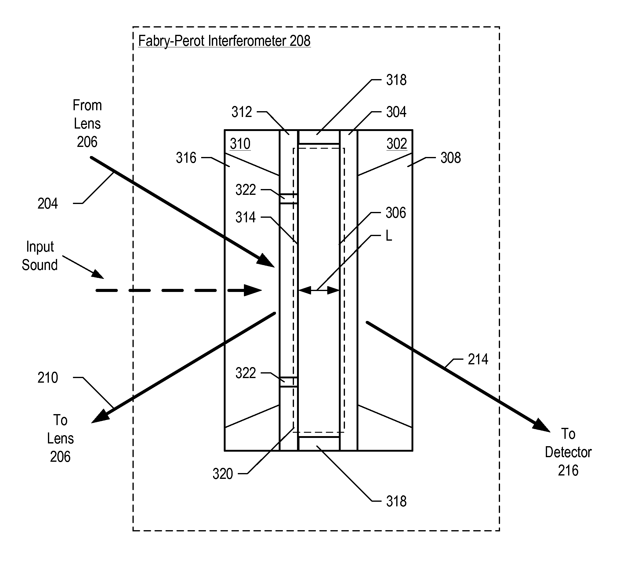
[0034] The following terms are defined for use in this Specification, including the appended claims: [0035] Fabry-Perot etalon means an optically-resonant cavity formed by two substantially parallel and substantially flat surfaces that are separated by a cavity length, wherein the cavity length is fixed. [0036] Fabry-Perot interferometer means an optically-resonant cavity formed by two substantially parallel and substantially flat surfaces that are separated by a cavity length, wherein the cavity length is not fixed. Examples include arrangements of plates wherein the cavity length is controllably-varied using an actuator, as well as arrangements wherein the cavity length can vary in response to a stimulus, such as incident acoustic energy. [0037] Cavity length means the instantaneous separation between two s...


PUM


Abstract

An optical displacement sensor is disclosed that provides a optical displacement sensor that includes a optically-resonant cavity tuned to an operating wavelength without some of the disadvantages for doing so in the prior art. An embodiment of the present invention tunes an operating wavelength used with a Fabry-Perot interferometer to develop a desired relationship between the wavelength and the Fabry-Perot interferometer's initial cavity length.

Description

FIELD OF THE INVENTION [0001] The present invention relates to displacement sensors in general, and, more particularly, to microphones. BACKGROUND OF THE INVENTION [0002] Displacement sensors, such as microphones and pressure sensors, are well-known. Displacement sensors based on capacitive, impedance, and optical measurements have been developed. Optical displacement sensors are particularly attractive as they overcome many of the limitations of capacitive and impedance measurement techniques, such as low sensitivity, the need for high-voltage biasing, poor electrical isolation, or response nonlinearities. [0003] Many optical-displacement sensors known in the prior art operate by detecting light reflected by an optical element that changes its reflectivity in response to an environmental stimulus, such as pressure differential, sound, vibration, etc. The detected light is converted into an electrical signal. This signal is a function of the reflectivity of the optical element, and,...

Claims


Application Information

Patent Timeline
Patent Type & Authority Applications(United States)
IPC IPC(8): G01B9/02
CPCG01L9/0079H04R25/505H04R23/008
Inventor CARR, DUSTIN WADE
Owner SYMPHONY ACOUSTICS
Why Eureka
Try Eureka