Cooling enclosure for maintaining commercial-off-the-shelf (COTS) equipment in vehicles

a technology for cooling enclosures and cots, which is applied in the direction of electric apparatus casings/cabinets/drawers, lighting and heating apparatus, instruments, etc., can solve the problems of difficult integration of cot equipment with systems designed to meet military specifications, difficult to efficiently provide the proper environment for cot equipment, and high cost of even slight modification. achieve the effect of reducing pressure drop

Active Publication Date: 2007-10-11
THE BOEING CO
View PDF48 Cites 41 Cited by
  • Summary
  • Abstract
  • Description
  • Claims
  • Application Information

AI Technical Summary

Benefits of technology

[0016] In another preferred embodiment, a baffle is created near the front of the enclosure and just upstream of the equipment in the enclosure. The baffles are positioned to direct the cooling air into the equipment from which the warmed air is discharged toward the rear of the enclosure. Thus, the enclosure contains a mixing plenum upstream from the equipment and a discharge plenum downstream from the equipment and that is formed between the equipment and the rear wall of the enclosure. Return plenums in the hollow side walls of the inner chamber complete a circuit for the cooling air to circulate between the mixing plenum and the exhaust plenum of the inner chamber. Fans, which may be provided with the enclosure, draw air from the exhaust plenum and cause it to flow to the mixing plenum thereby creating a one-way flow path within the enclosure. The circulating air flows through the equipment from the mixing plenum to the exhaust plenum and thence through the return plenums to return to the mixing plenum. These plenums, particularly the exhaust plenum, reduce the pressure drop associated with the cooling air flowing along the circulation path. The resulting minimal pressure drop in turn allows the low power fans that may be provided with the pieces of equipment to supply the motive force to move the cooling air instead of relying on the fans or other equipment of the aircraft ECS. By creating the baffle in the manner described herein, the enclosure is easy to reconfigure for changing the mix of equipment therein by way of modifying the baffle. This is a much simpler solution than reconfiguring the typical ducted plenums found in previously available avionics cabinets or racks. The configuration of the current embodiment also makes it possible to have a single temperature control point, preferably in the mixing plenum, for the cooling air circulating within the enclosure. Accordingly, the current embodiment provides accurate temperature control of the cabinet and parallel flow of cooling air to each piece of equipment within the enclosure.

Problems solved by technology

As a result, integration of the COTS equipment with systems designed to meet military specifications has proven to be difficult, especially for aircraft applications.
Previously available attempts to solve these difficulties use unique equipment and are therefore expensive to modify even slightly.
Without the unique equipment, however, it is difficult to efficiently provide the proper environment for the COTS equipment.
Because COTS equipment typically has very low limits on its air exhaust temperature COTS equipment is inefficient to cool.
The low cooling efficiency in turn leads to very high cooling air flow demands (and therefore fan power consumption).
The low temperature differential also makes transferring the heat off the plane very difficult.
Additionally, changing the ducting configuration within a cabinet is costly and may involve changes to the configuration of the overall ECS system to accommodate even a single new piece of COTS equipment.
In addition to temperature control, humidity control can also be a challenge because many aircraft ground operations are conducted in humid environments with the cabin doors open.
In such situations, elevated external ambient temperatures can limit cooling capacity while excessive humidity can cause moisture and condensation to be present in the aircraft.
Unfortunately, a humidification system with the capacity to control the humidity for all of the equipment onboard a typical aircraft is prohibitively heavy.

Method used


Image

  • Cooling enclosure for maintaining commercial-off-the-shelf (COTS) equipment in vehicles
  • Cooling enclosure for maintaining commercial-off-the-shelf (COTS) equipment in vehicles
  • Cooling enclosure for maintaining commercial-off-the-shelf (COTS) equipment in vehicles

Examples


Embodiment Construction

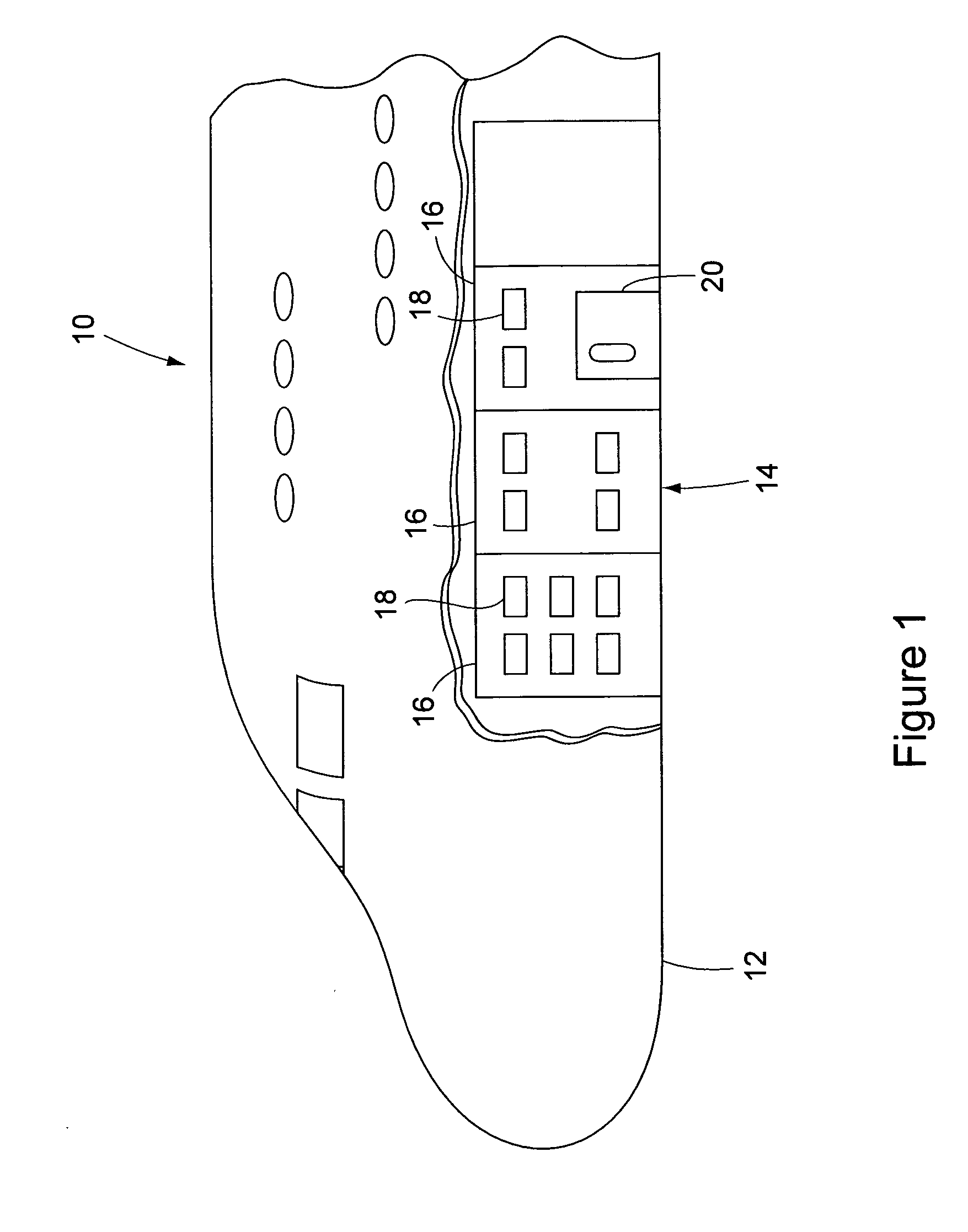
[0025] Referring to the accompanying drawings in which like reference numbers indicate like elements, FIG. 1 illustrates an exemplary aircraft that is constructed in accordance with the principles of the present invention.

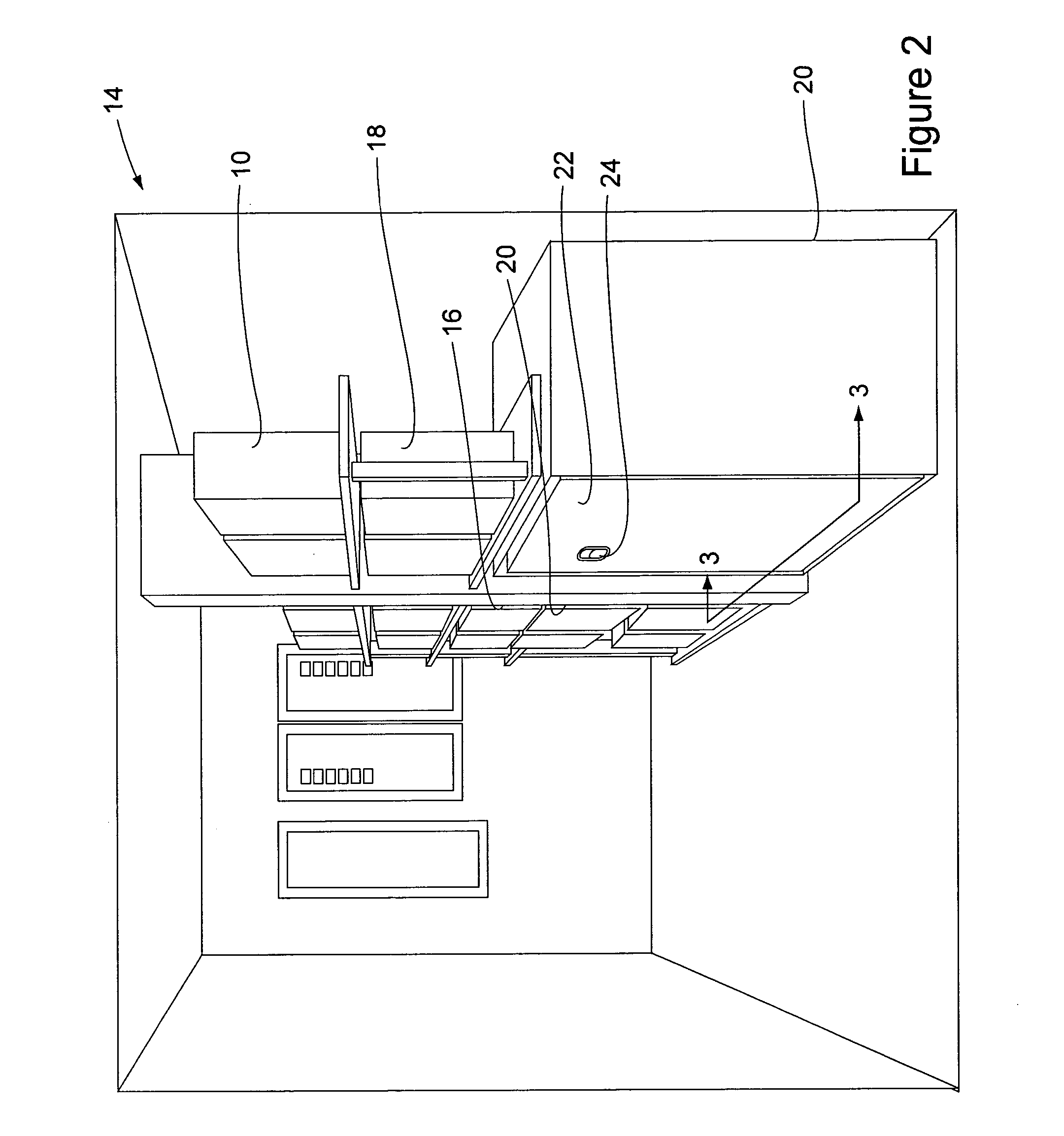
[0026] More particularly, FIG. 1 shows a model 747 commercial aircraft 10 that is available from The Boeing Company of Chicago, Ill.. The aircraft 10 is exemplary and could be any aircraft either civilian, military, or otherwise. FIG. 1 also shows a lower lobe 12 of the aircraft 10, an avionics bay 14, several electronic equipment racks 16, numerous pieces of electrical equipment 18, numerous shelves 19, and an equipment enclosure 20 of the present invention. The lower lobe 12 includes the avionics bay 14 in a convenient location near the crew cabin so that the crew can access the electrical equipment 18 that resides in the avionics bay. The avionics bay 14 is maintained at a pre-selected temperature by an environmental control system (ECS) of the aircraft 10. The...


PUM


Abstract

Apparatus and methods for thermal conditioning equipment. In a preferred embodiment, an equipment enclosure comprises a body, a wall, a fluid port, and a fixture. The body defines an outer plenum and an inner chamber in the latter of which the fixture retains the equipment. The wall, which is between the outer plenum and the inner chamber, isolates the thermally conditioned first fluid from a second fluid in the inner chamber. Since the wall is thermally conductive it allows heat to be transferred between the outer plenum and the inner chamber. The fluid port is in communication with the outer plenum to allow the thermally conditioned first fluid to flow into the outer plenum. Baffle plates are also provided to distribute flow of the second fluid to the equipment.

Description

FIELD OF THE INVENTION [0001] This invention relates generally to environmental control systems and, more particularly, to environmental control systems for commercial-off-the-shelf (COTS) electronic equipment for use onboard mobile platforms such as aircraft. BACKGROUND OF THE INVENTION [0002] Commercial-Off-the-Shelf (COTS) equipment is increasingly being used in military environments to take advantage of advancements in commercially available technology. By definition, COTS equipment has no or comparatively relaxed design environmental requirements. As a result, integration of the COTS equipment with systems designed to meet military specifications has proven to be difficult, especially for aircraft applications. A comprehensive solution to this integration challenge that accommodates all of the military operational requirements and FAA flight requirements has yet to be developed. [0003] Such a solution would preferably allow for unforeseen variability in the COTS equipment and a...

Claims


Application Information

Patent Timeline
Patent Type & Authority Applications(United States)
IPC IPC(8): H05K7/20F28D15/00F04D29/44
CPCF28F2009/222H05K7/202
Inventor HARDER, DANIELLEONARD, CHARLES F.
Owner THE BOEING CO
Why Eureka
Try Eureka