
Catalytic flow-through fast light off ceramic substrate and method of manufacture

a technology of ceramic substrates and flow-through ceramics, which is applied in the direction of physical/chemical process catalysts, gas-gas reaction processes, separation processes, etc., can solve the problems of increasing the time required for light off, affecting the and reducing the amount of time required. , to achieve the effect of effective catalytic effect of automotive pollutants

Active Publication Date: 2007-10-11
CORNING INC
View PDF7 Cites 29 Cited by
  • Summary
  • Abstract
  • Description
  • Claims
  • Application Information

AI Technical Summary

Benefits of technology

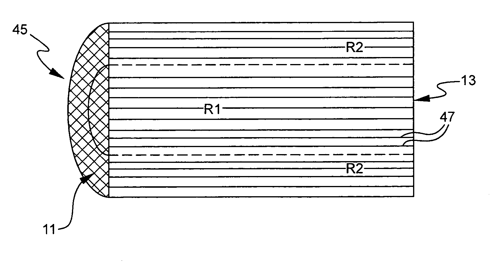
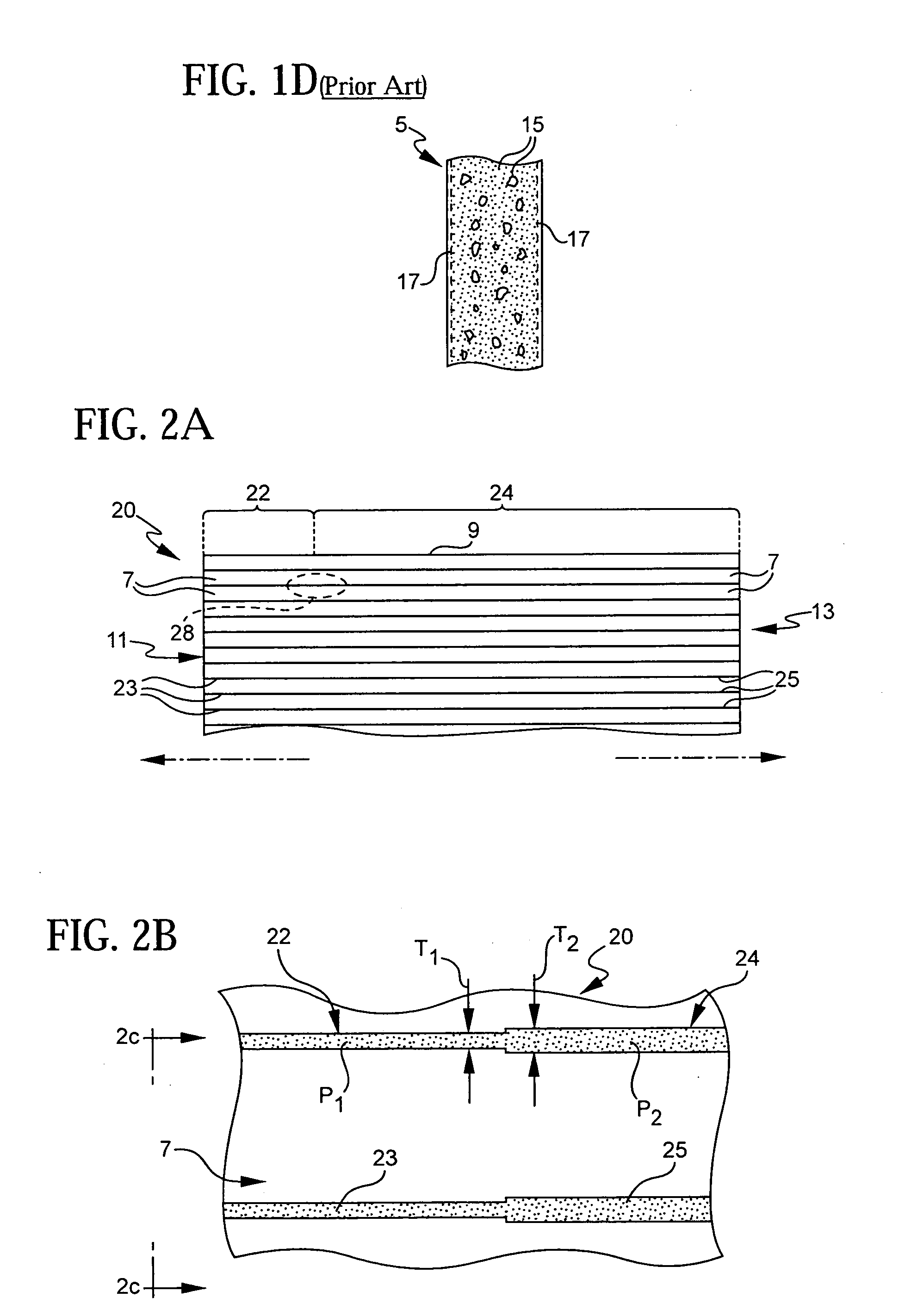
[0008]In either of the aforementioned embodiments of the invention, the thermal mass of the walls may also increase in a radial direction orthogonal to the axis of the ceramic body. Increasing the thermal mass (and hence either increasing the thickness or lowering the porosity) of the web walls in such a radial direction advantageously increases both the strength of the resulting ceramic body, as well as the time required for cool-down of the web walls, which in turn reduces the stresses caused by thermal gradients in the body that can sometimes lead to cracking.
[0010]All embodiments of the invention are advantageously capable of reducing the light off time of the resulting catalytic, flow-through ceramic substrate by 10-25% without significantly compromising the mechanical strength and durability of the resulting substrate.

Problems solved by technology

The use of walls of such thickness also results in a reasonably short light off time of about 24 seconds (i.e., the time it takes before the webs reach the required 250° C. before the catalyst impregnated over the walls begins to oxidize CO to CO2, and to effectively disassociate NOx into N2 and O2).
First, such substrates are structurally weaker than more conventional, thicker walled substrates.
Hence, they are more prone to crack or to break during both the manufacturing process and the “canning” process when they are locked into a metal enclosure that forms part of the automotive exhaust system.
Secondly, in operation, the thin walls may be prone to erosion along the face of the inlet end of the substrate due to the impingement of the particulate material entrained in the stream of exhaust gases.
The resulting “sand blast” effect may weaken the already fragile structure, but may also render the inlet portion of the substrate ineffective in catalyzing pollutants by eroding away the catalytic coating on the cell walls, or even the walls themselves.
However, the applicants have observed that these substrates suffer from the same deficiencies as thin-walled substrates do, i.e., insufficient mechanical strength, and excessive erosion near the inlet end.

Method used


Image

  • Catalytic flow-through fast light off ceramic substrate and method of manufacture
  • Catalytic flow-through fast light off ceramic substrate and method of manufacture
  • Catalytic flow-through fast light off ceramic substrate and method of manufacture

Examples


Embodiment Construction

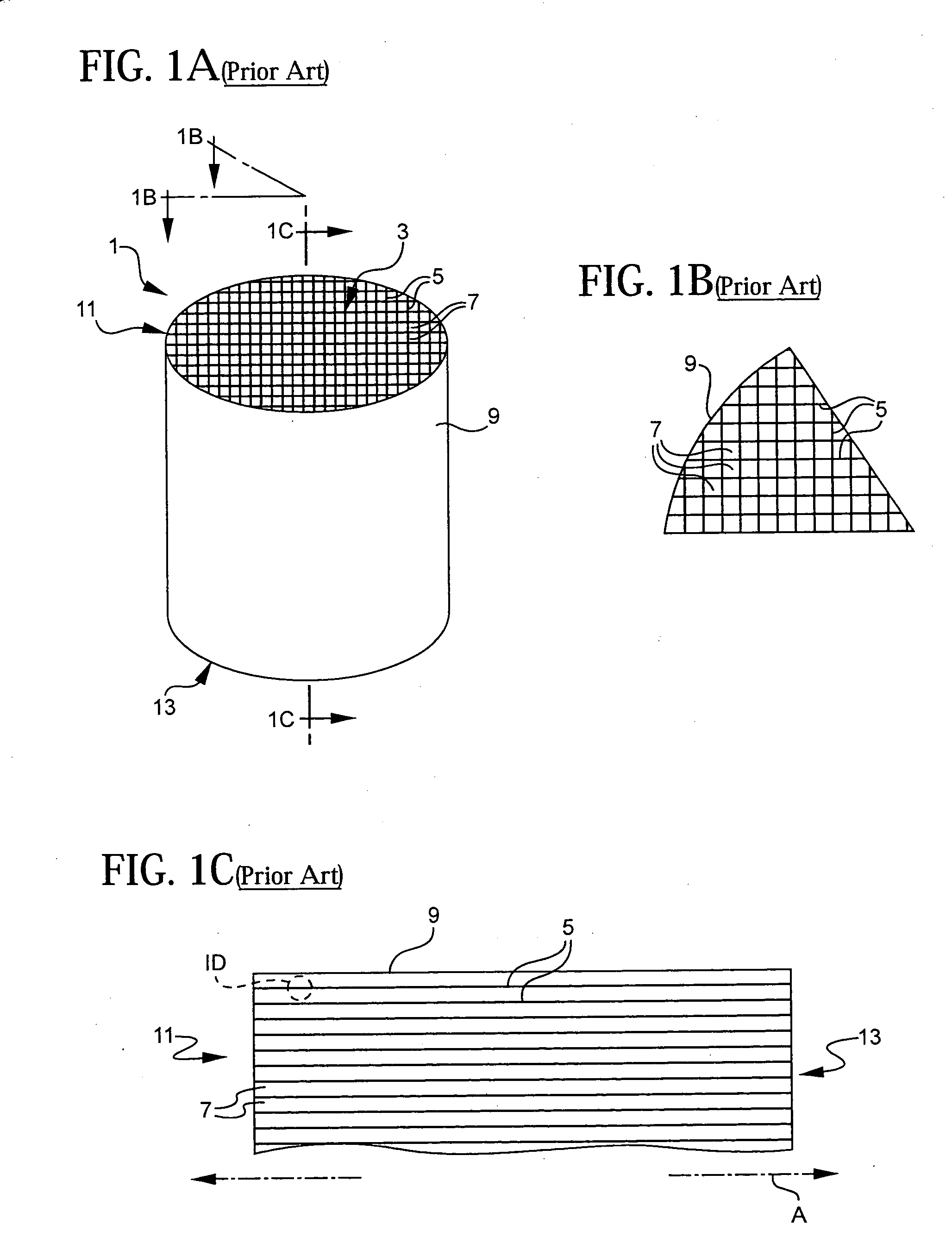
[0024]With reference now to FIGS. 1A through 1D, the invention is applicable to ceramic substrate 1 of the type used as automotive catalytic converters. Such substrates including network 3 of walls typically between about 2.0 and 6.0 mils thick which define a plurality of flow-through cell channels 7. While the cell channels 7 are illustrated as having a square cross-section in FIG. 1B, that may just as easily be octagonal, hexagonal or some other polygonal shape. The flow-through cell channels are typically between about 0.02 and 0.05 inches in width, and are arranged at a cell density of between about 300-900 cells per square inch. The substrate 1 further includes an extruded outer skin 9 which is typically cylindrical, and has a thickness of approximately three to four times that of the web walls 5. The resulting cylindrical structure of the substrate 1 has an inlet end 11, and an outlet end 13 which are opposed from one another along the axis A illustrated in FIG. 1C. In this ap...


PUM

PropertyMeasurementUnit
porosityaaaaaaaaaa
porosityaaaaaaaaaa
thickaaaaaaaaaa

Abstract

A fast light off flow-through ceramic substrate is provided that is particularly adapted for use as a catalytic converter. The substrate is formed from a body of ceramic material having axially opposing inlet and outlet ends for receiving and expelling the flow of automotive exhaust gas, respectively. The body contains a network of walls coated with a catalyst that define axially-oriented flow-through cell channels. The average thermal mass (ATM1) of a first axial region of the walls adjacent to the inlet end is at least 20% less than the average thermal mass (ATMTOT) of all of the walls. The lower average thermal mass of the walls in the first region advantageously shortens the light off time for the catalyst within the substrate to effectively neutralize automotive pollutants. The reduction of the average thermal mass in only the first axial region of the walls advantageously maintains the strength of the resulting body of ceramic material, and further increases the cool down time of the body.

Description

FIELD OF THE INVENTION[0001]This invention generally relates to ceramic honeycomb structures of the type used in vehicular exhaust systems, and is specifically concerned with a catalytic flow-through ceramic substrate having fast light off characteristics.BACKGROUND OF THE INVENTION[0002]Ceramic honeycomb structures of the type used in vehicular exhaust systems are known in the prior art. Such structures generally comprise a network of interconnected walls (webs) that form a matrix of elongated, gas-conducting cells which are typically square or hexagonal in shape. The cell matrix is surrounded by a cylindrical outer skin to form a can-shaped structure having opposing inlet and outlet ends for receiving and expelling exhaust gases through the matrix of cells. Such ceramic honeycomb structures find particular application as catalyst-supporting substrates for automobile exhaust systems.[0003]When such ceramic honeycomb structures are used as automotive catalytic converters, the cell w...

Claims


Application Information

Patent Timeline
Patent Type & Authority Applications(United States)
IPC IPC(8): H01L21/336
CPCB01D46/2418B01D46/2425B01D46/2466B01D46/247B01D2046/2433Y02T10/20B01J35/0006B01J35/0026B01J35/04F01N3/0222B01D2046/2496Y02T10/12B01D46/2498B01D46/24491B01D46/2484B01D46/2482B01J35/31B01J35/19B01J35/56B01D46/2474B01D46/2429
Inventor FISCHER, MICHAELFU, XIAODONG ROBERTHOUSE, KEITH LEONARDKETCHAM, THOMAS DALELAMBERT, DAVID WARD
Owner CORNING INC
Learn More