Eureka AIR delivers breakthrough ideas for toughest innovation challenges, trusted by R&D personnel around the world.

Support Prosthesis

Inactive Publication Date: 2007-10-11
FLIEDNER THILO
View PDF3 Cites 20 Cited by
  • Summary
  • Abstract
  • Description
  • Claims
  • Application Information

AI Technical Summary

Benefits of technology

[0010] The support prosthesis for vessels or intracorporeal lumens has a tubular casing comprising a metallic support structure with support elements extending transversely to the longitudinal direction. The support elements, which are arranged next to one another in the longitudinal direction, are connected to the tubular casing by at least one connecting element which is made of a resilient, non-metallic material and extends in the longitudinal direction. The connecting elements also allow the support elements to stretch on radial expansion and set the support elements apart from one another on radial expansion.
[0011] Non-metallic materials can have such a high modulus of elasticity that the connecting elements do not have to be configured as spring elements by specific shaping. On the contrary, coarse structures can also be selected for the connecting elements. Coarse structures of this type are easy to produce and are able to set the support elements apart from one another on radial expansion. In general, the non-metallic connecting elements are fastened to the support elements by adhesion. The points of contact between the non-metallic connecting elements and the support elements are in this case natural predetermined breaking points, so the connecting elements are at least partially detached from the support elements on radial expansion and can release the support elements for the stretching movement. However, even if there is a positive locking connection between the connecting elements and support elements, the support elements can be pulled out from sufficiently soft connecting elements and therefore become detached from the connecting elements. Despite the coarse configuration of the connecting elements, the stretching movement of the support elements is therefore not be impeded.
[0012] In addition, non-metallic materials can have sufficient resilience to allow bending of the support prosthesis in curved vessels and to follow a large number of bending processes of the vessel without breaking. Non-metallic materials can also be biodegradable and dissolve in a patient's body. It is also conceivable to add to the non-metallic material medicaments which are issued to the vessel wall after the introduction of the support prosthesis. Medicaments of this type can, in particular, serve to inhibit inflammatory reactions.
[0015] In a further embodiment, the support structure is free from support elements which encircle the circumference of the casing in a closed manner. This prevents any extensive eddy currents from being induced in the support structure. The support structure therefore cannot be heated by the eddy currents occurring on the application of strong magnetic fields. In addition, the use of examination processes such as nuclear magnetic resonance cannot result in image artefacts due to shielding effects.
[0016] A support structure which is free from support elements encircling the circumference of the casing in a closed manner is obtained, for example, if the support structure is formed by a support helix. In this case, high supporting forces can be applied to the wall of the vessel without the risk of magnetic fields inducing eddy currents in the support structure.

Problems solved by technology

However, even if there is a positive locking connection between the connecting elements and support elements, the support elements can be pulled out from sufficiently soft connecting elements and therefore become detached from the connecting elements.

Method used


Image

  • Support Prosthesis
  • Support Prosthesis
  • Support Prosthesis

Examples


Embodiment Construction

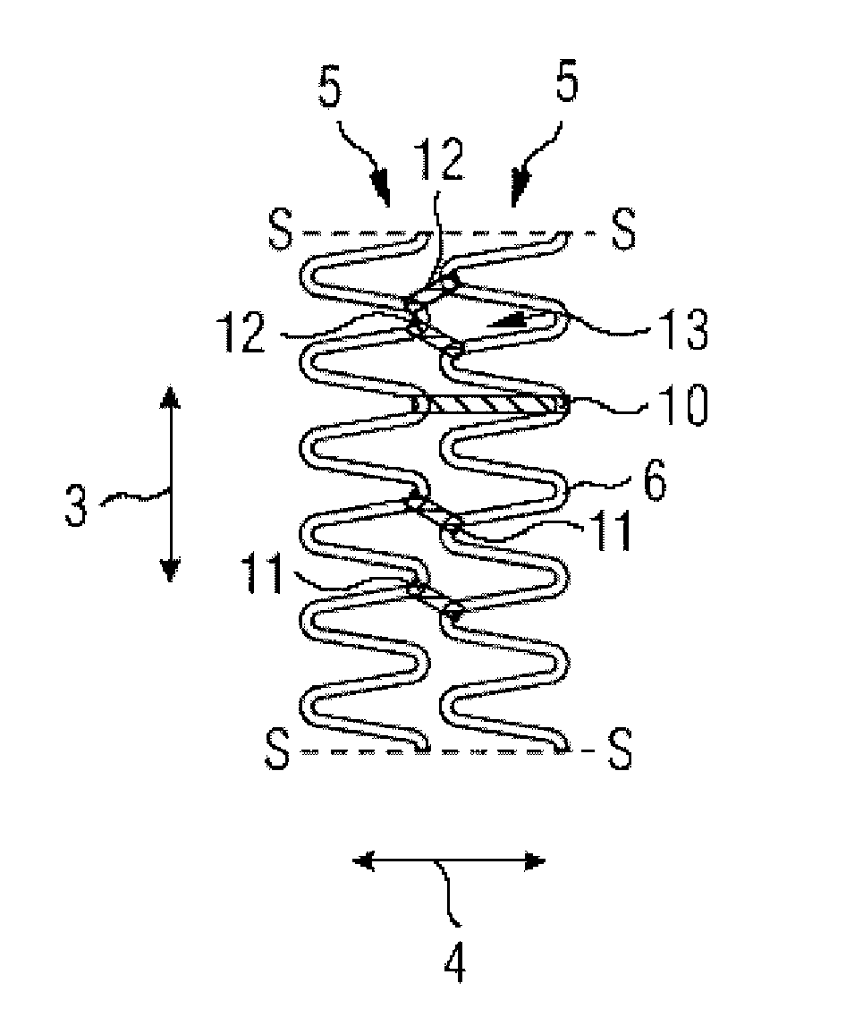
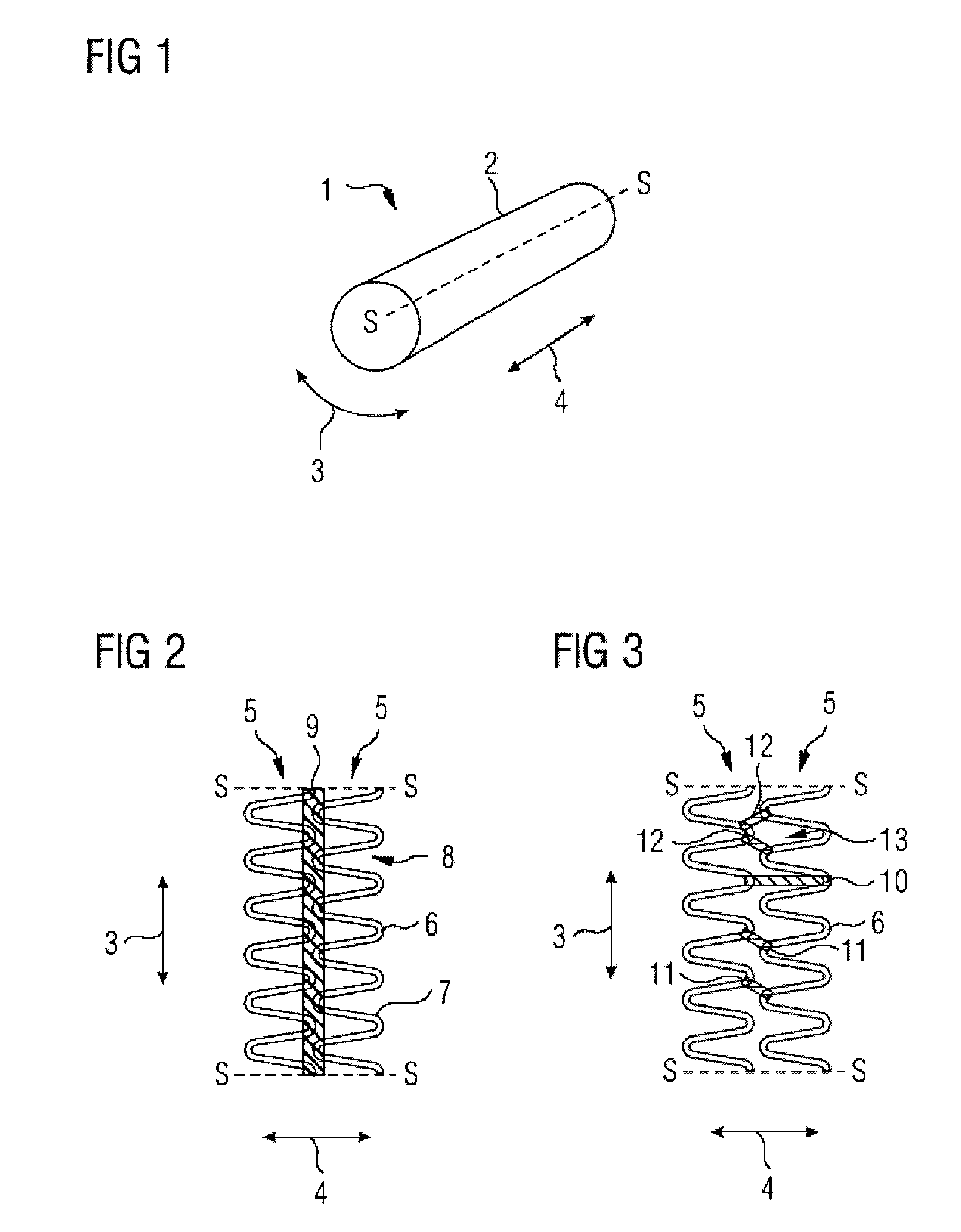
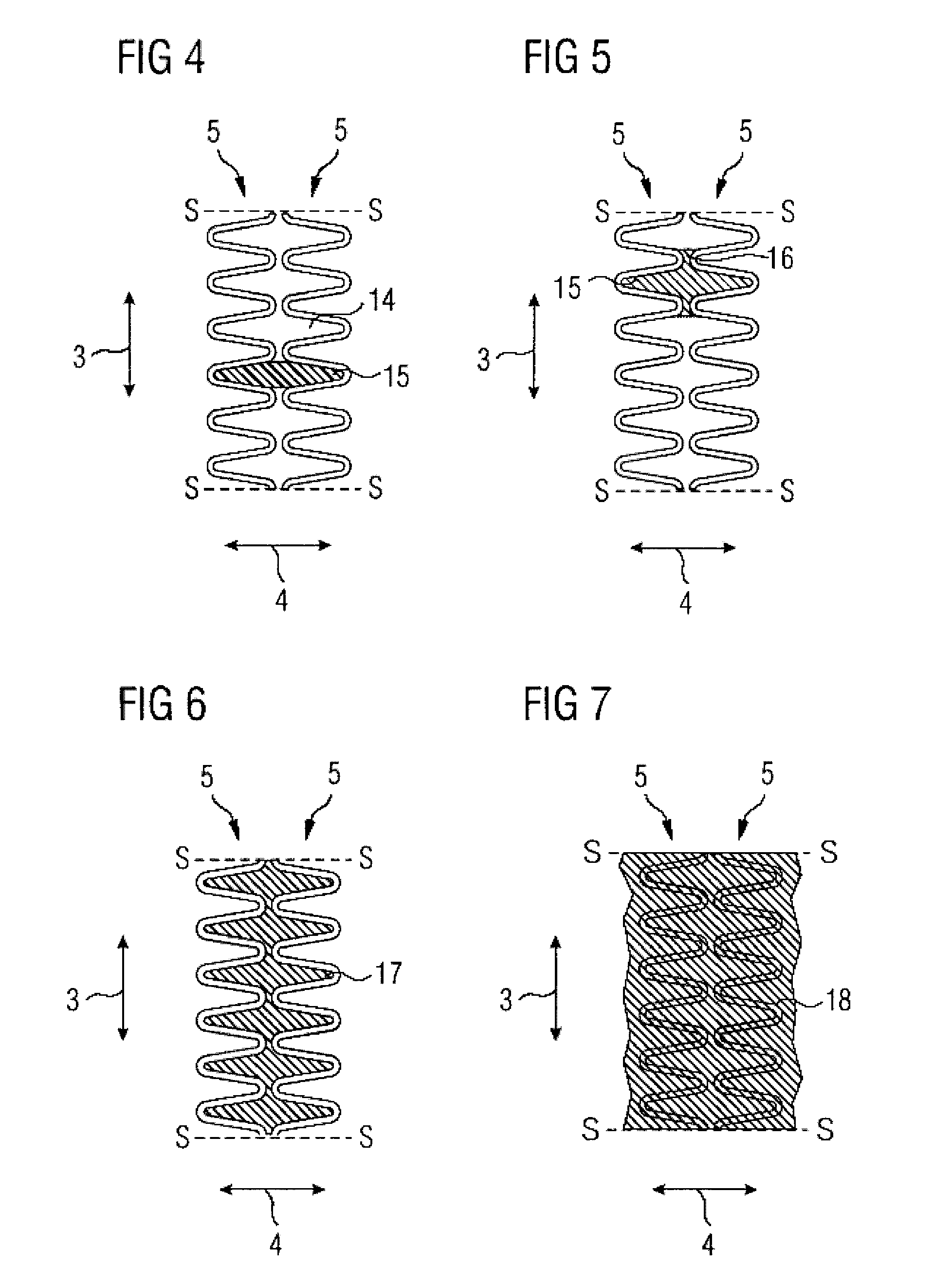
[0030]FIG. 1 is a perspective view of a stent 1 comprising a tubular casing 2. The casing 2 has a large number of support rings 5 which extend in a circumferential direction 3, are arranged next to one another in a longitudinal direction 4 and are shown in the following FIG. 2 to 7 on an enlarged scale and cut open along a sectional line S-S.

[0031] The support rings 5 have a meandering, in particular an undulating, course. In the case of the support rings 5 shown in FIG. 2 to 7, which display an undulating course, curves 6 are connected by straight support struts 7. A curve 6 and two adjacent support struts 7 form, in each case, a loop 8. Successive loops 8 therefore share a respective support strut 7.

[0032] For implantation, the stent 1 is crimped onto what is known as a balloon catheter. The balloon catheter is then brought to the point to be widened of the vessel to be treated, where it is expanded. This stretches the support rings 5 in the circumferential direction 3. In parti...


PUM


Abstract

A support prosthesis for vessels or intracorporeal lumens has a large number of support rings which are connected in a longitudinal direction using non-metallic connecting elements.

Description

CROSS-REFERENCE TO RELATED APPLICATIONS [0001] The present application is a continuation of pending International patent application PCT / DE2005 / 001633 filed on Sep. 16, 2005 which designates the United States and claims priority from German patent application 10 2004 045 224.5 filed on Sep. 17, 2004, the content of which is incorporated herein by reference.FIELD OF THE INVENTION [0002] The invention relates to a support prosthesis for vessels or intracorporeal lumens with a tubular casing which can expand in the radial direction and has a metallic support structure with support elements extending transversely to the longitudinal direction. BACKGROUND OF THE INVENTION [0003] A support prosthesis of this type is known from DE 101 53 340 A1. The known support prosthesis has a large number of support rings connected by intermediate rings which are expandable in the longitudinal direction. Both the support rings and the intermediate rings have a meandering course. Support prostheses of t...

Claims


Application Information

Patent Timeline
Patent Type & Authority Applications(United States)
IPC IPC(8): A61F2/88A61F2/90A61F2/07A61F2/82A61F2/89A61F2/91A61F2/915
CPCA61F2/07A61F2/88A61F2/91A61F2/915A61F2210/0076A61F2002/91533A61F2002/91558A61F2250/0071A61F2/89A61F2002/826
Inventor FLIEDNER, THILO
Owner FLIEDNER THILO
Why Eureka
Eureka Blog
Learn More