Air-fuel ratio detection apparatus of internal combustion engine

a technology of air-fuel ratio and detection apparatus, which is applied in the direction of machines/engines, electrical control, non-mechanical valves, etc., can solve the problems of reducing the accuracy of cylinder air-fuel ratio control to degrade emission and fuel consumption, and the accuracy of estimating the air-fuel ratio of each cylinder may be remarkably reduced, so as to achieve the effect of reducing the estimation accuracy of the air-fuel ratio of each cylinder

Inactive Publication Date: 2007-10-18
DENSO CORP
View PDF5 Cites 50 Cited by
  • Summary
  • Abstract
  • Description
  • Claims
  • Application Information

AI Technical Summary

Benefits of technology

[0018]In this construction, when the operating state of the internal combustion engine is suddenly changed to bring the engine operating state to the operating state in which the estimation of a cylinder air-fuel ratio is difficult, the state variable can be reset and returned to an initial value. Thus, when the air-fuel ratio of each cylinder is estimated next time, the air-fuel ratio

Problems solved by technology

However, the exhaust gas does not collide uniformly with the air-fuel ratio sensor, so it can be thought that the air-fuel ratio of only a specific cylinder is different from those of the other cylinders.
In this case, there is a possibility that the air-fuel ratio of the specific cylinder is substantially different from an air-fuel ratio when the engine is viewed as a whole and hence deviates from the stoichiometric air-f

Method used


Image

  • Air-fuel ratio detection apparatus of internal combustion engine
  • Air-fuel ratio detection apparatus of internal combustion engine
  • Air-fuel ratio detection apparatus of internal combustion engine

Examples


first embodiment

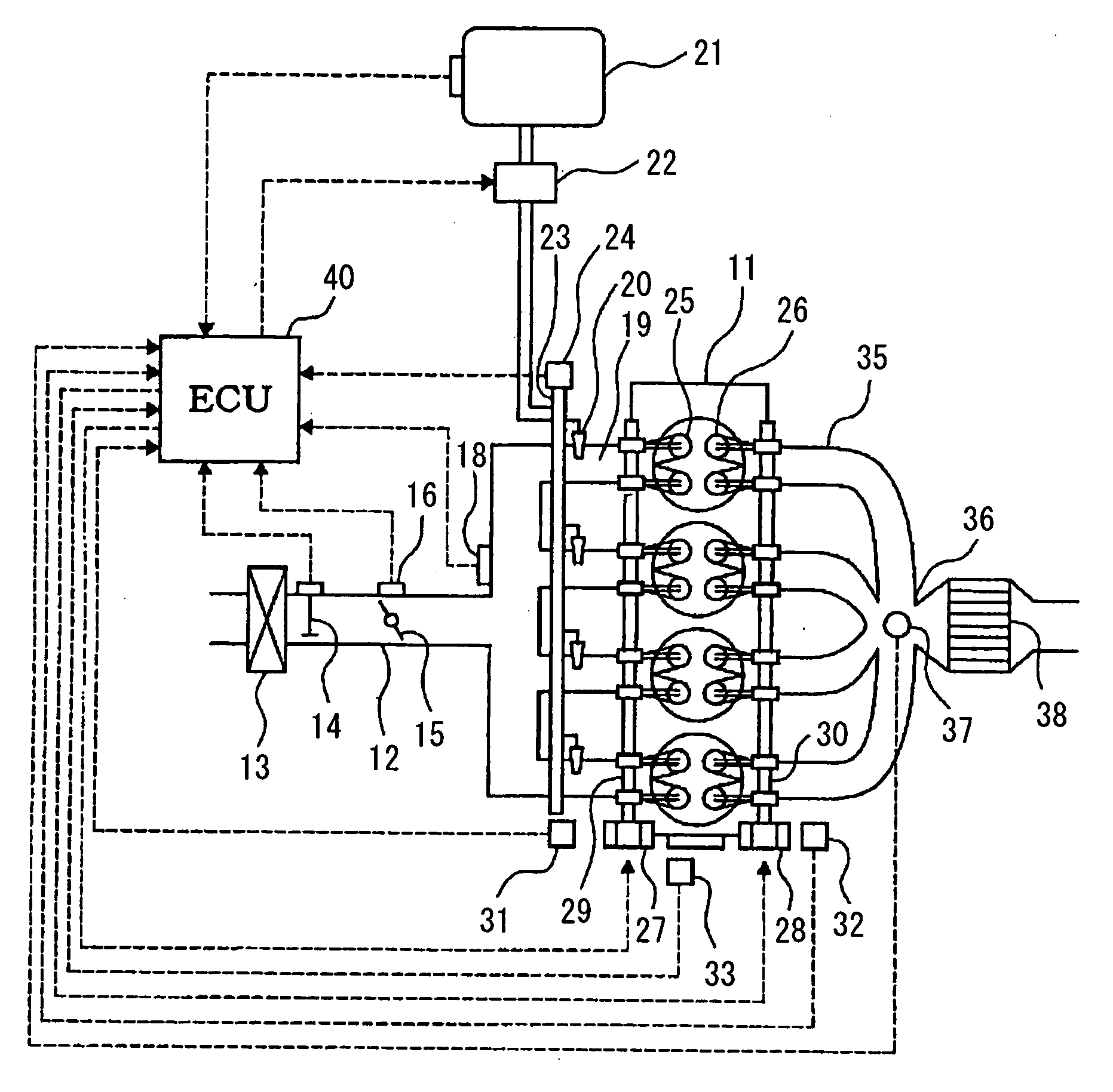
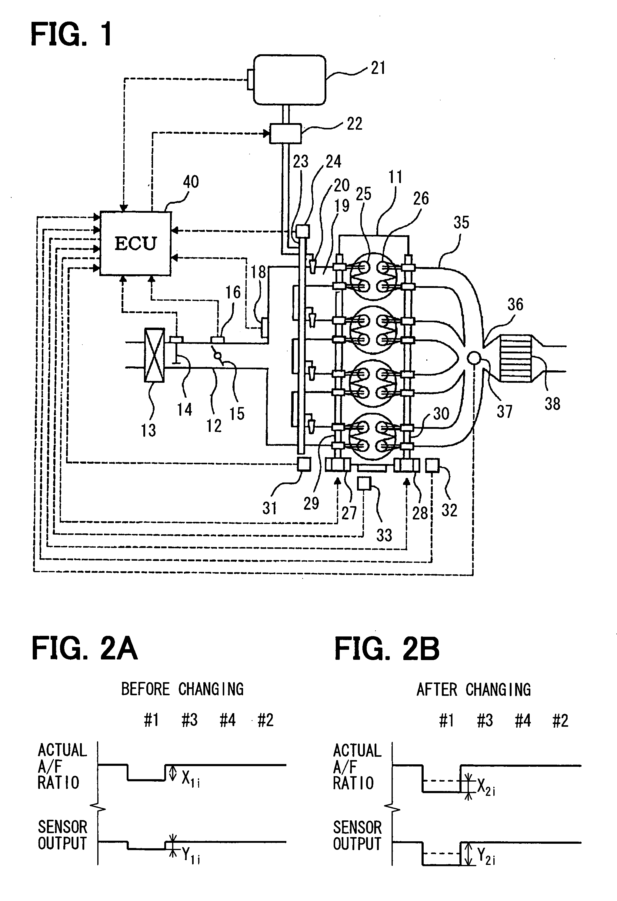
[0045]A first embodiment of the present invention will be described with reference to FIG. 1 to FIG. 4. First, the general construction of an engine control system will be described with reference to FIG. 1. An air cleaner 13 is disposed in the upstream portion of an intake pipe 12 of an internal combustion engine, for example, an in-line four-cylinder engine 11. An air flow meter 14 for detecting an intake air quantity is disposed downstream of the air cleaner 13. A throttle valve 15 having its opening controlled by a motor or the like and a throttle position sensor 16 for detecting a throttle opening are disposed downstream of the air flow meter 14.

[0046]Moreover, a surge tank 17 is disposed downstream of the throttle valve 15. The surge tank 17 is provided with an intake pipe pressure sensor 18 for detecting an intake pipe pressure. The surge tank 17 is provided with an intake manifold 19 for introducing air into the respective cylinders of the engine 11. Fuel injection valves 20...

second embodiment

[0065]Next, another embodiment will be described with reference to FIG. 6. When the processing of this flow chart is performed, the presence or absence of abnormality caused by the time degradation or the clogging of injection port of the injector, the depositing of an EGR port, and the characteristic abnormalities of WL and WT can be detected by a computed deviation in the air-fuel ratio. The processing of this flow chart is performed at intervals of a specified crank angle.

[0066]When the processing of this flow chart is performed, it is determined in step 1031 whether it is a cylinder in which a cylinder difference is to be detected this time and whether the execution conditions of cylinder difference estimation determination are satisfied. Here, that the execution conditions of cylinder difference estimation determination are satisfied means, as described above, that the engine operating state is steady and that the air-fuel ratio sensor is active. It is recommendable to determin...

third embodiment

[0072]A third embodiment of the present invention will be described with reference to FIG. 8 to FIG. 11.

[0073]In this third embodiment, the ECU 40 estimates the air-fuel ratio of each cylinder on the basis of the detected value of the air-fuel sensor 37 by the use of a model of estimating a cylinder air-fuel ratio when the specified execution conditions of cylinder air-fuel ratio control are satisfied; the detected value being the actual air-fuel ratio of exhaust gas flowing through the exhaust gas merging section 36. Further, the ECU 40 computes a fuel correction quantity (fuel correction factor) of each cylinder according to the deviation between the estimated air-fuel ratio of each cylinder and the target air-fuel ratio. Still further, the ECU 40 corrects the fuel injection quantity of each cylinder by the use of the fuel correction quantity of each cylinder and the learned value of a cylinder air-fuel correction quantity of each cylinder, the cylinder air-fuel correction quantit...


PUM


Abstract

In a multi-cylinder engine, to compute the air-fuel ratio of each cylinder by an air-fuel ratio sensor disposed in an exhaust pipe, a cylinder is determined by a crank angle detected by a crank angle sensor. A deviation in the air-fuel ratio of each cylinder is detected on the basis of the output signal of the air-fuel ratio sensor disposed in the exhaust pipe and the forcibly changed quantity of the air-fuel ratio.

Description

CROSS-REFERENCE TO RELATED APPLICATION[0001]This application is based on Japanese Patent Applications No. 2006-110366 filed on Apr. 13, 2006, No. 2006-143031 filed on May 23, 2006, and No. 2006-184135 filed on Jul. 4, 2006, the disclosures of which are incorporated herein by reference.FIELD OF THE INVENTION[0002]The present invention relates to an air-fuel ratio detection apparatus of an internal combustion engine. The apparatus detects the air-fuel ratio of exhaust gas of each cylinder on the basis of the signal of an air-fuel ratio sensor disposed in an exhaust pipe in a multi-cylinder engine.BACKGROUND OF THE INVENTION[0003]In an exhaust emission control system of an engine, a three-way catalyst is disposed in an exhaust pipe and exhaust gas is cleaned by this three-way catalyst. When the air-fuel ratio of the exhaust gas is controlled to a stoichiometric air-fuel ratio, the three-way catalyst disposed in the exhaust pipe can efficiently clean the exhaust gas. For this reason, an...

Claims


Application Information

Patent Timeline
IPC IPC(8): F02D41/00F01N3/00
CPCF01L9/04Y02T10/18F01N11/007F02D13/0207F02D13/0215F02D13/06F02D41/008F02D41/0085F02D41/0087F02D41/123F02D41/1458F02D41/22F02D41/2454F02D2041/001F02D2041/1415F01N3/10F01L9/20Y02T10/12
Inventor MITSUDA, TETSUJISAGISAKA, YASUOOKAMOTO, AKIHIROHIRATA, YASUOYAMADA, EIJIROU
Owner DENSO CORP
Why Eureka
Try Eureka