Flat Cable

a cable and flat technology, applied in the field of flat cables, can solve the problems of reducing the distance between the cable and the ground, the interference of radiation and emission is significantly reduced the mechanical loadability is higher, and the bending properties are better

Active Publication Date: 2007-10-18
W L GORE & ASSOC GMBH
View PDF18 Cites 96 Cited by
  • Summary
  • Abstract
  • Description
  • Claims
  • Application Information

AI Technical Summary

Benefits of technology

[0018] Since common-mode disturbances, for example, crosstalk, are filtered out during differential signal transmission with signal conductor pairs, as already mentioned, and disturbances from radiation and emission are significantly reduced, no additional cable shielding is required. Consequently, higher mechanical loadability and better bending properties are achieved with a flat cable according to the invention than the ordinary one-layer flat cables have, which have shielding layers, in addition to the signal conductors.
[0019] In one embodiment of the invention with signal conductor pairs and corresponding ground conductors, narrow conductors are situated in one of the two conductor planes and wide, flat conductors in the other conductor plane. In this case, two adjacent narrow conductors of one conductor plane form a signal conductor pair, whereas the wide, flat conductor in the other conductor plane serves as a reference or ground potential conductor for an adjacent pair of narrow signal conductors. The wide, flat conductors then

Problems solved by technology

However, there is also the possibility of producing th

Method used


Image

  • Flat Cable
  • Flat Cable
  • Flat Cable

Examples


Embodiment Construction

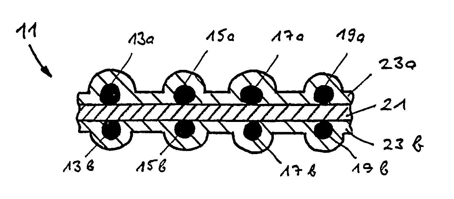
[0038] In the following explanation of the drawings terms, like vertical, horizontal, upper, lower, left and right are used, which refer only to the depiction in the correspondingly treated figure, for the correspondingly treated flat cable, but have no absolute meaning and no longer apply in a position different than the one depicted.

[0039]FIG. 1 shows in a cross-sectional view part of the width of a flat cable 1 according to the invention with electrical round conductors 13a, 15a, 17a and 19a, which are situated in an upper conductor plane, and electrical round conductors 13b, 15b, 17b and 19b, which are situated in a lower conductor plane. When this flat cable is used for differential signal transmission, the electrical conductors 13a, 13b form a first differential signal conductor pair, the electrical conductors 15a and 15b form a second differential signal conductor pair, etc. A practical embodiment of such a flat cable can have more or less than the four signal conductor pair...


PUM

PropertyMeasurementUnit
Thicknessaaaaaaaaaa
Adhesivityaaaaaaaaaa
Widthaaaaaaaaaa

Abstract

A flat cable having at least two conductor planes, in which a number of electrical conductors running in the longitudinal direction of the cable are arranged, in which the electrical conductors in the flat cable thickness direction and/or in the flat cable width direction are kept at a defined distance from each other by means of a central insulation layer of predetermined thickness acting as a spacer insulator and are electrically insulated and positioned relative to each other and to the flat cable exterior by means of an outer insulation layer.

Description

FIELD OF THE INVENTION [0001] The invention relates to a flat cable, its use and a method for its production. BACKGROUND OF THE INVENTION [0002] Flat cables, which not only have the smallest possible dimensions and high permanent flexibility, but also permit transmission of very high data rates with minimal transit time differences, for example, in the range of 2.5 Gbit / s, are required for certain applications. Such applications include mobile telephones, PDAs (personal digital system) or small computers called palmtops and laptops, which have parts that can be tilted and / or rotated relative to each other, between which high-speed data transmission is required. Because of the small dimensions, especially in the case of mobile telephones and PDAs, such data connections must be produced via flat cables with the smallest possible dimensions, even micro flat cables. [0003] Particularly reliable data transmission is obtained with so-called differential signal transmission, in which the d...

Claims


Application Information

Patent Timeline
IPC IPC(8): H01B7/08H01B13/06
CPCH01B7/0838Y10T29/49117Y10T29/53243H01B7/0869
Inventor REICHERT, RUDOLFMUELLER, JOACHIM
Owner W L GORE & ASSOC GMBH
Why Eureka
Try Eureka