Automotive Radar

a technology for autos and radars, applied in the field of autos, can solve the problems of deteriorating the radiation properties of antennas, large radar size, poor detection accuracy, etc., and achieve the effects of reducing sidelobes, preventing road clutter, and improving low relative velocity

Inactive Publication Date: 2007-10-18
HITACHI LTD
View PDF15 Cites 92 Cited by
  • Summary
  • Abstract
  • Description
  • Claims
  • Application Information

AI Technical Summary

Benefits of technology

[0017] For the automotive radar of the present invention configured as above, it is possible to allow passage of co-polarized waves of the linear polarized waves through the slit plate and block cross-polarized waves which are main constituents of sidelobes, and consequently, thereby enabling reduction of the sidelobes and prevention of the road clutter. Together, particularly, as for a sidelobe that vertically strikes the road surface when the radar is mounted in a vehicle, co-polarized waves, which are weak, as well as the cross-polarized waves, which are main constituents of the sidelobe, can be reduced greatly

Problems solved by technology

Therefore, the S/N ratio, when the vehicle equipped with the radar is traveling, is expressed as (St−Nr) (in this case, St is a value with regard to a velocity difference of 0.4), which becomes greatly worse than the S/N ratio, when the vehicle is at a stop, thus resulting in problems such as poor accuracy of a detected distance and erroneous detection.
As for the above-mentioned technique for preventing the road clutter by placing a metal plate in the lower part of the front of the

Method used


Image

  • Automotive Radar
  • Automotive Radar
  • Automotive Radar

Examples


Embodiment Construction

[0033] The automotive radar of the present invention will now be described in further detail with reference to several embodiments thereof.

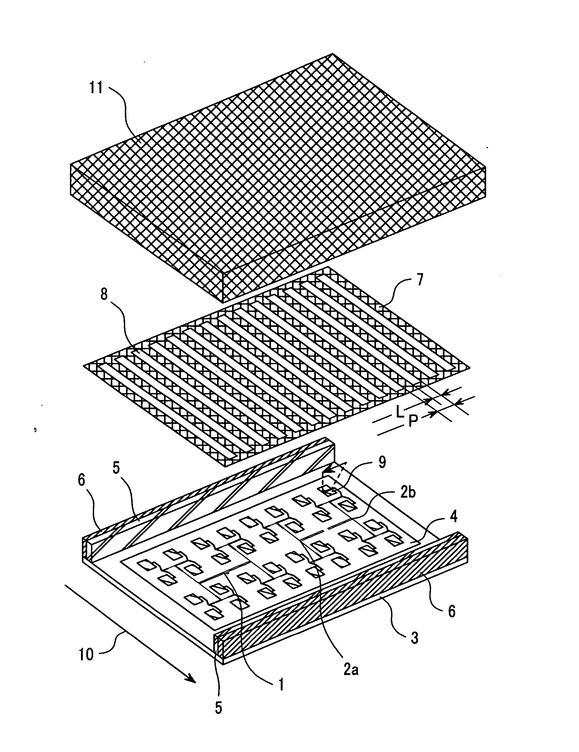
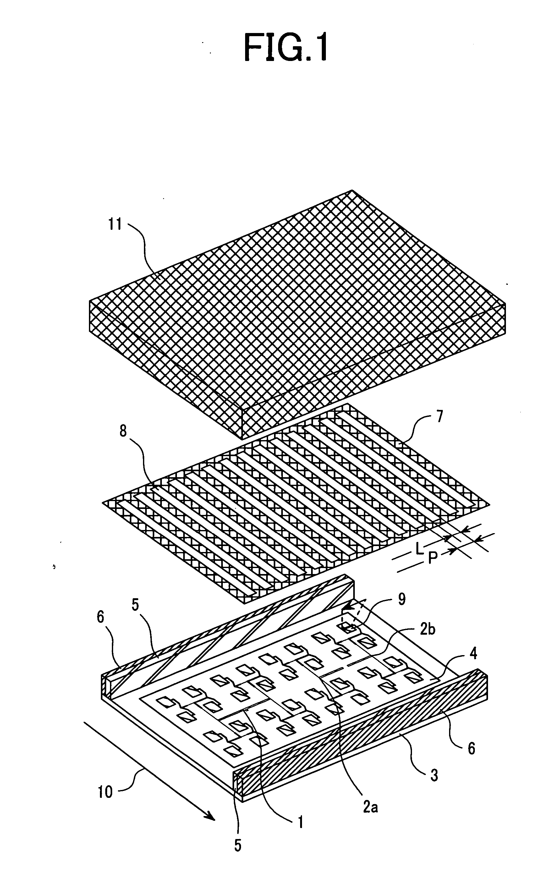
[0034] A first embodiment of the present invention is shown in FIG. 1. An arrow 10 denotes the direction facing toward the road surface, when the automotive radar has been installed in the vehicle. The radar of the present invention employs a patch antenna that radiates linear polarized waves, using patch elements as radiating elements. The radar transmits a transmit signal from a transmitting patch antenna 1, receives a signal reflected by a target via a receiving patch antenna 2a and a receiving patch antenna 2b, and detects the velocity, distance, and direction of the target from the received signal.

[0035] The transmitting patch antenna 1 and the receiving patch antennas 2a, 2b constructed on a dielectric substrate 4 are disposed on an antenna plate 3 made of a metal and covered by a radome 11 made of a dielectric material. Along both longit...


PUM


Abstract

A small and light automotive radar having a high detection performance by preventing the road clutter and its in-vehicle positioning is optional is provided. The automotive radar comprises an antenna 1, 2a, 2b equipped with at least one radiating element which radiates linear polarized radio waves; a slit plate 7 which is a metal plate in which a plurality of slits are defined, placed in front of the surface of the antenna; radio wave absorbers 5 provided between the antenna and the slit plate; and a transceiver device which supplies transmit signals to the antenna to radiate radio waves and, from signals acquired by receiving reflection waves which are returned waves of the radio waves reflected by an obstruction, detects a direction in which the obstruction exists.

Description

FIELD OF THE INVENTION [0001] The present invention relates to an automotive radar that is mounted on a mobile object such as a motor vehicle to detect a direction in which an obstruction exists, a relative distance to some other mobile object, a relative velocity of the some other mobile object, etc. BACKGROUND OF THE INVENTION [0002] Automotive radars using millimeter waves draw attention as optimal radars for preventing a car crash, tracking an object while traveling, and the like, since they are less affected by climate conditions such as rain, fog, and snow, as well as dust and noise, as compared with ultrasonic radars and laser radars. [0003] In the above application, as is illustrated in FIG. 12, an automotive millimeter wave radar 20 is installed to the front of a mobile object 21 and transmit signals are radiated through a mainlobe mb from an antenna toward a vehicle under detection (hereinafter referred to as a “target”) 22. By observing frequency difference, phase differe...

Claims


Application Information

Patent Timeline
IPC IPC(8): H01Q1/32G01S7/03G01S13/931H01Q15/00H01Q17/00H01Q19/02H01Q19/28H01Q21/06
CPCG01S7/032G01S13/931H01Q1/3233H01Q17/001G01S2013/9321H01Q19/28H01Q21/065H01Q15/0013G01S2013/9375H01Q19/028G01S7/024G01S7/2813H01Q1/425H01Q1/52H01Q15/24H01Q17/00G01S2013/93271H04L27/26265G01S7/027
Inventor SHINODA, HIROSHIKONDOU, HIROSHI
Owner HITACHI LTD
Why Eureka
Try Eureka