TV broadcast receiver

US20070242167A1Inactive Publication Date: 2007-10-18FUNAI ELECTRIC CO LTD

Image

  • TV broadcast receiver
  • TV broadcast receiver
  • TV broadcast receiver

Examples


Embodiment Construction

[0047]The detailed description set forth below in connection with the appended drawings is intended as a description of presently preferred embodiments of the invention and is not intended to represent the only forms in which the present invention may be constructed and or utilized.

[0048]For purposes of illustration, programs and other executable program components are illustrated herein as discrete blocks, although it is recognized that such programs and components may reside at various times in different storage components, and are executed by the data processor(s) of the computers.

[0049]We will describe below the embodiment of the present invention according to the following order.

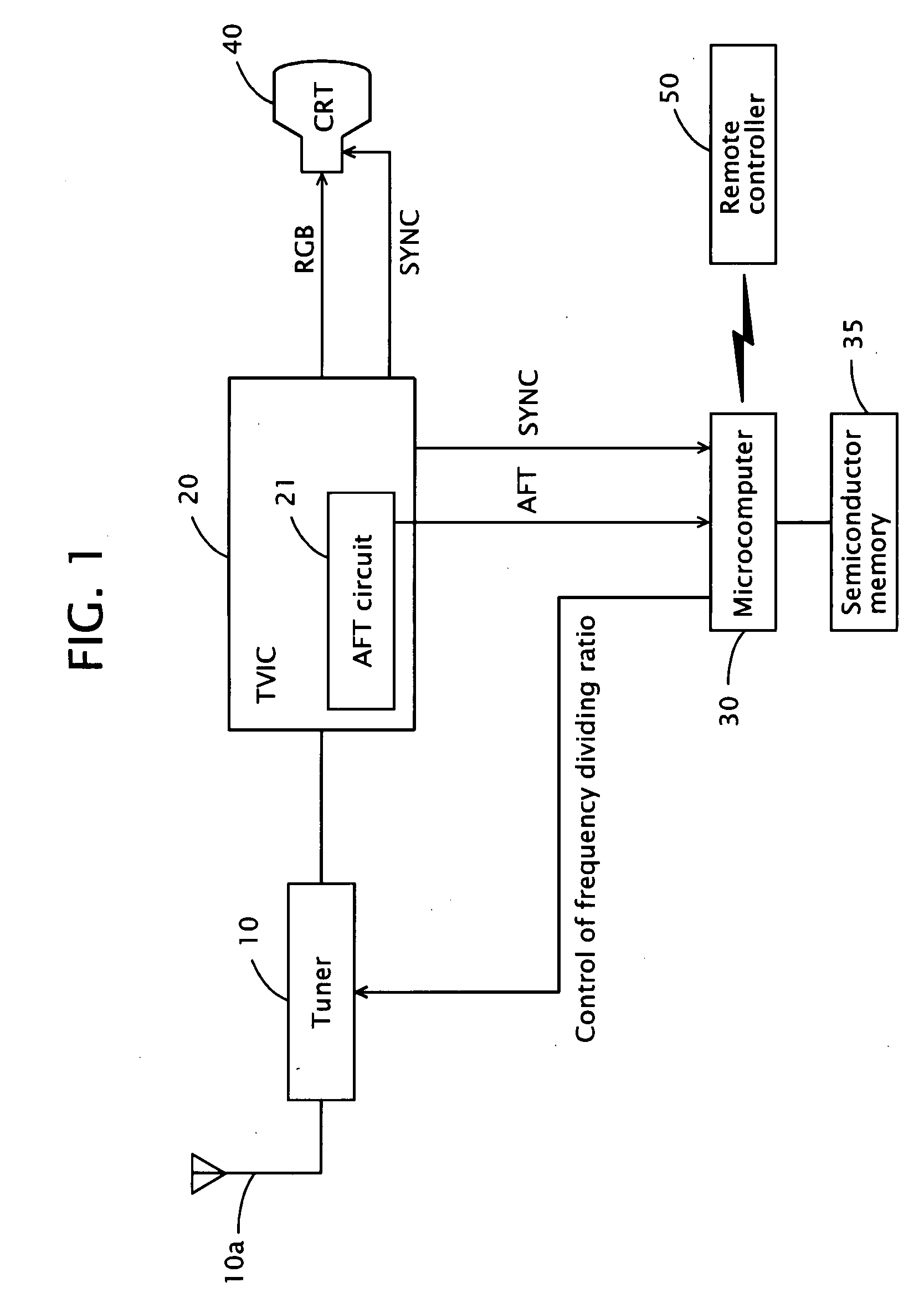
(1) Schematic configuration of the TV broadcast receiver,

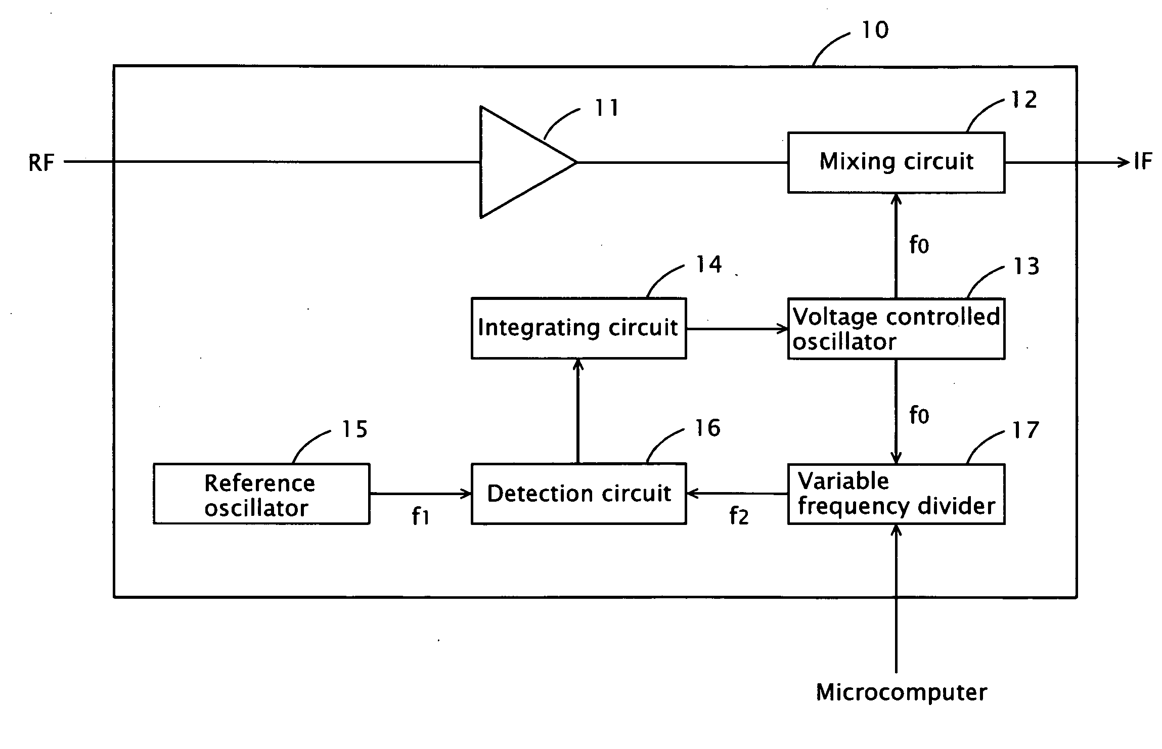
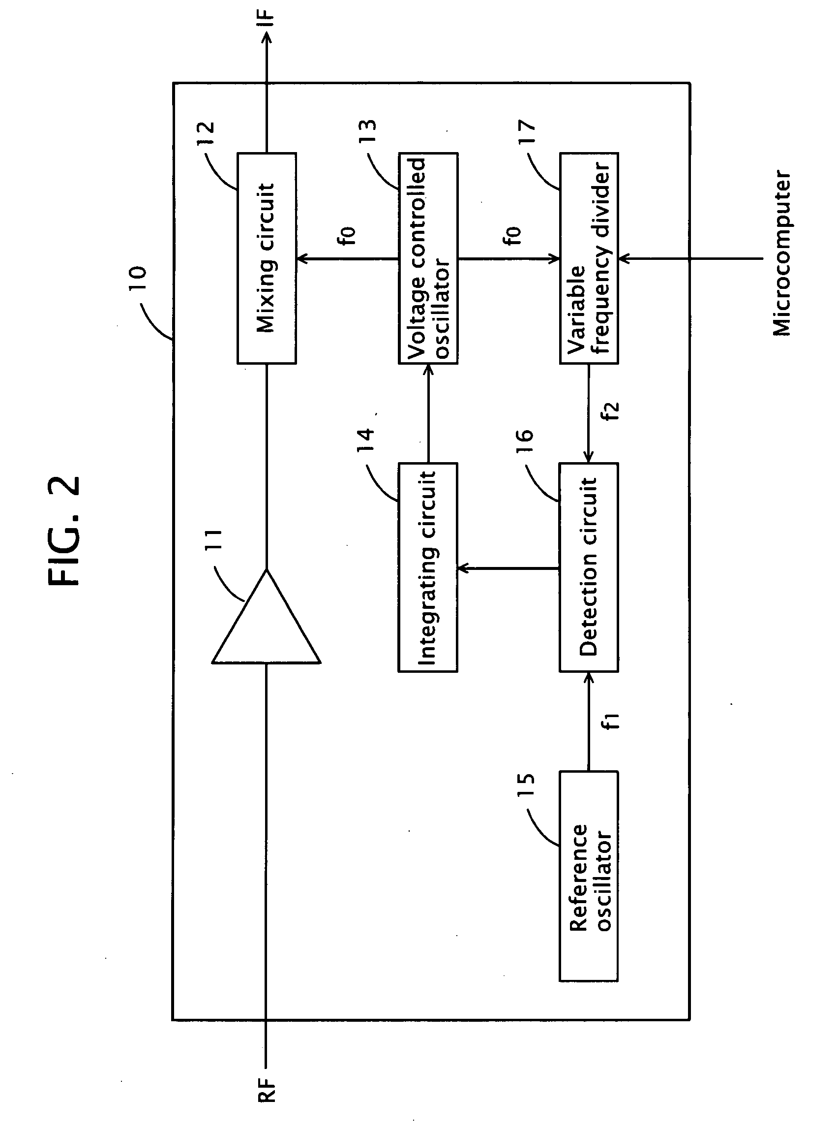
(2) Schematic configuration of the tuner circuit,

(3) Processing of the microcomputer for presetting channels

(4) First variation of the processing of the microcomputer for presetting channels

(5) Second variation of the processing of the microcomput...


PUM


Abstract

In the course of the channel presetting process, the central frequency is set by a step of 1 MHz within the range from the minimum frequency in the VHF band channel plan to the maximum frequency of the VHF band adopted in the place of destination for the scheduled shipment of the TV broadcast receivers, attempts are made to detect broadcast signals by changing frequency within a range of 1.5 MHz to the high frequency side and 0.5 MHz to the low frequency side from the central frequency, and the frequencies of the detected broadcast signals are stored in the semiconductor memory.

Description

CROSS-REFERENCES TO RELATED APPLICATIONS[0001]The present application is related to the Japanese Patent Application No. 2006-113676, filed Apr. 17, 2006, the entire disclosure of which is expressly incorporated by reference herein.BACKGROUND OF THE INVENTION[0002]1. Field of the Invention[0003]The present invention relates to a TV broadcast receiver.[0004]2. Description of the Related Art[0005]In recent years, a majority of tuners used in TV broadcast receivers are frequency synthesizer-type PLL tuners, and generally any frequency inputted from a microcomputer is made to syntonize the locally oscillated frequency at the predetermined frequency to receive the desired channel. For tuning in a station with this PLL tuner, a broadcast signal is searched automatically in advance based on a channel plan for each country (for each region).[0006]If the channel plan is a standard one, the standard step wherein the frequency between the respective channels in the VHF band and the UHF band is ...

Claims


Application Information

Patent Timeline
18 Oct 2007
Publication
US20070242167A1
IPC
H04N5/44; H04N5/50; H04B1/16
CPC
H03J1/0075; H04N5/50; H04N5/46; H03J7/02
Inventors
SUZUKI, HIROTSUGU