Zinc-based film manipulation for an optical filter

a technology of optical filter and zinc film, applied in the direction of optical filter, optics, instruments, etc., can solve the problems of color change distracting, difficult to effectively control, and different factors regarding the design of pdp filter may conflict, and achieve the effect of stable process

Active Publication Date: 2007-10-18
SOUTHWALL TECH INC
View PDF11 Cites 45 Cited by
  • Summary
  • Abstract
  • Description
  • Claims
  • Application Information

AI Technical Summary

Benefits of technology

[0016] The use of zinc-based films to form a dielectric layer provides a significant reduction in cost as compared to the formation of indium-based dielectric layers. Additionally, the tailoring of the percentages of zinc within the different zinc-based films that form a layer achieves performance advantages. One surprising result of forming the dielectric layer or layers in accordance with the first embodiment is that there is a smaller change in color as a function of viewing angle, as compared to above-cited approaches. Another surprising result is that the sheet resistance is lowered. For example, a sheet resistance of 1.25 ohms / square has been achieved. In the formation of a dielectric film, the first deposited zinc-based film has a percentage of zinc that is selected on the basis of factors that include process stabilization. The preferred range of this layer is twenty-five percent to seventy-five percent, but it is even more preferably approximately fifty percent (plus or minus five percent). The selection of the percentage of zinc in the subsequently formed zinc-based film is based upon factors that include establishing target properties of a seeding layer for the subsequently formed metallic layer. This second percentage of zinc is intentionally greater than the first percentage. The second percentage is in the range of eighty percent to one hundred percent, and is preferably approximately ninety percent.
[0018] As a further enhancement, the dielectric layer may be formed of an initial film that is indium-based, such as InOx. This initial film may be used in order to protect the previously formed metallic layer. By forming the indium-based film with a flow of high content hydrogen, an underlying silver layer is protected from oxidizing and the process is stable.

Problems solved by technology

Unfortunately, whether designing an optical filter for coating windows or coating a PDP, there are tradeoffs among the different factors.
Thus, modifying a filter to increase conditions with respect to one desired property may conflict with maintaining a target level for another property.
Any color change is distracting when a display is viewed from a close distance, where the color of the display appears to change across the surface.
In particular, it is objectionable if the “red-green” component of color, Ra*, changes substantially with angle.
As previously noted, different factors regarding the design of PDP filters may conflict.
Infrared radiation is relatively close in wavelength to red and is therefore difficult to effectively control while simultaneously obtaining low reflection in the red region of the spectrum (i.e., 620-700 nm).
Controlling reflection within the red region of the light spectrum is rendered even more difficult by the need for a low sheet resistance in the PDP filter 12.
The requirement for lower sheet resistance increases the color problem for etalon EMI filters.
The transmission bandwidth of the filter becomes narrower as the conductive layers become thicker, resulting in both an increase in the red reflection and a loss of color bandwidth in transmission.
There is a conflict between the tendency of Etalon filters to show red reflection at different viewing angles and the generally expected appearance of consumer products.
This objectionable reflection limits the thickness of the conductive layers used in such filters.
In addition, there is a large color shift with incidence angle, which creates an apparent color difference across the screen for a large screen viewed at a close distance.
Thus, despite the suitability of the coating for some Class B EMI applications, this coating may be considered cosmetically unacceptable.

Method used


Image

  • Zinc-based film manipulation for an optical filter
  • Zinc-based film manipulation for an optical filter
  • Zinc-based film manipulation for an optical filter

Examples


Embodiment Construction

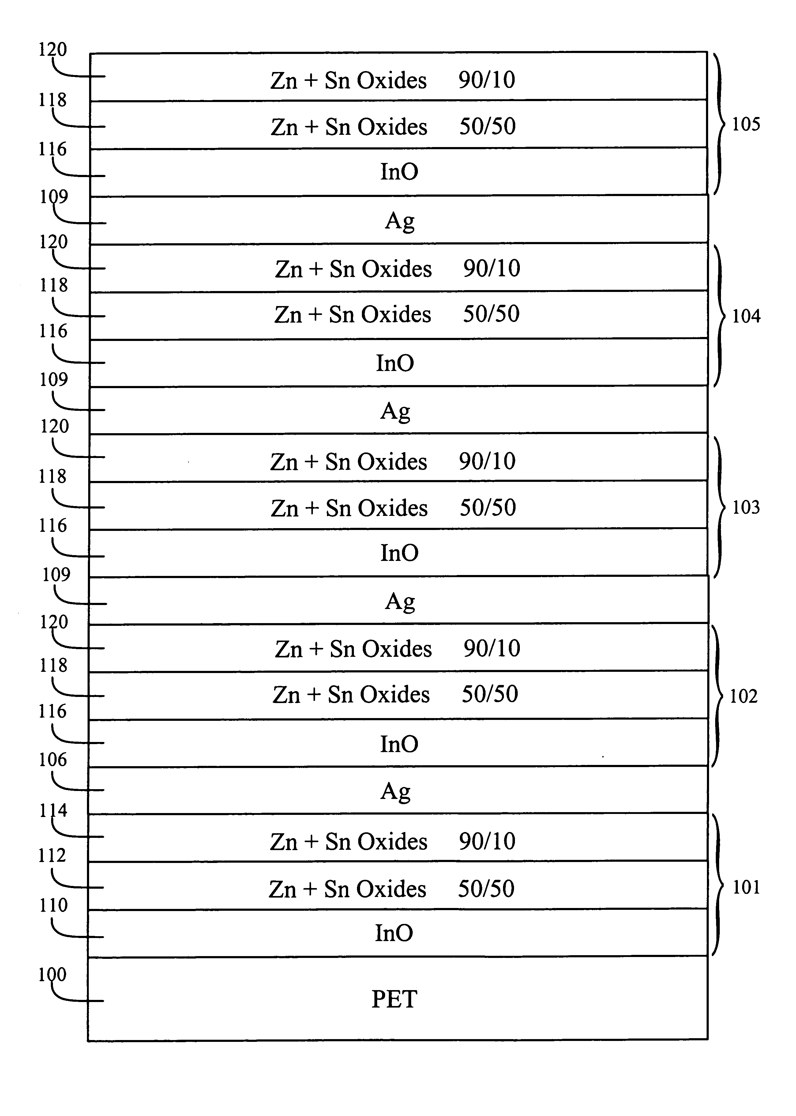
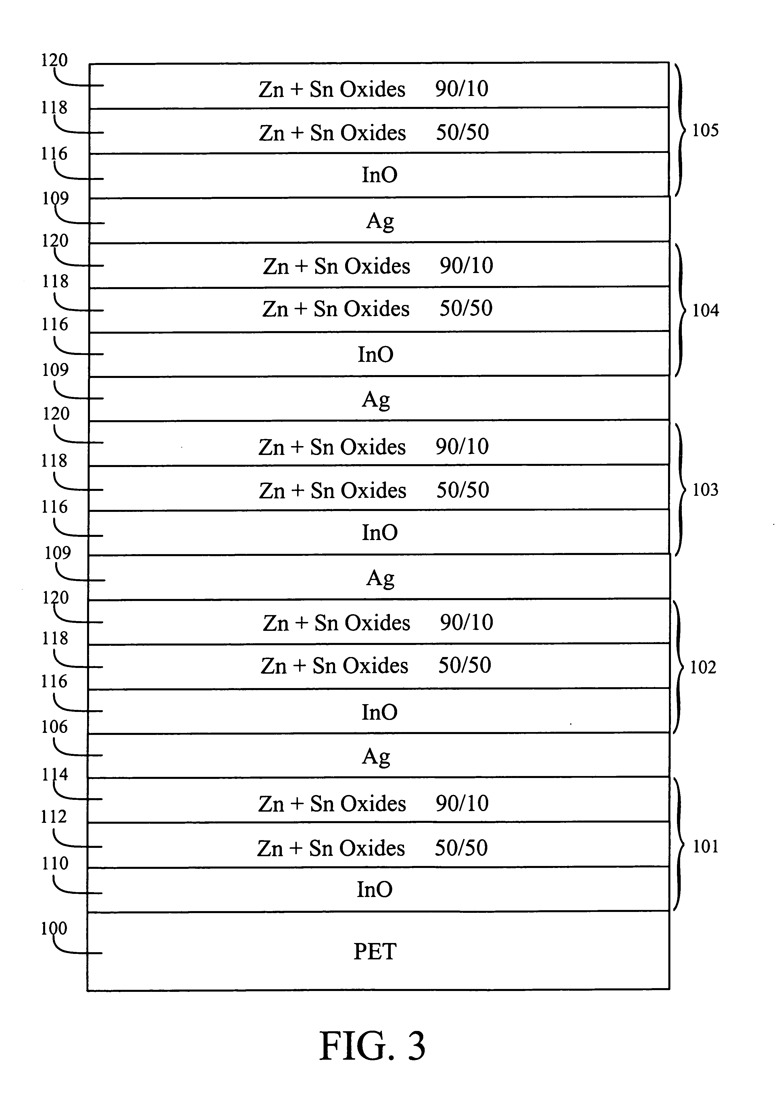
[0025] With reference to FIG. 3, an alternating pattern of layers is formed on a flexible polymeric substrate 100. The polymeric substrate may be PET having a thickness of twenty-five to one hundred microns. While not shown in FIG. 3, the side of the substrate opposite to the alternating pattern may include a layer of adhesive and a release strip. The release strip is easily removed from the adhesive, allowing the adhesive layer to be used to couple a substrate and its layers to a member for which filtering is desired. For example, the filtering arrangement may be adhered to a plasma display panel or to a window. In another embodiment, the alternating pattern is formed directly on the member for which filtering is desired. For example, it may be necessary to pass the panel through a sputter chamber for depositing the materials which form the layers.

[0026]FIG. 3 illustrates the preferred embodiment in which there are five dielectric layers 101, 102, 103, 104 and 105 and four metal l...


PUM

PropertyMeasurementUnit
wavelengthaaaaaaaaaa
sheet resistanceaaaaaaaaaa

Abstract

An optical filter is formed of a layer stack that includes metallic layers and dielectric layers, with at least one dielectric layer being defined by more than one zinc-based film. These zinc-based films have different percentages of zinc. The selections of the percentages are based upon the positions of the films within the dielectric layer. An unexpectedly low sheet resistance is available if the zinc-based film that immediately precedes forming a metallic layer has a percentage of zinc in the range of 80 percent to next to 100 percent. Process stabilization and manufacturing cost are provided by placing the percentage of the lower zinc-based film closer to 50 percent (25-75). Process stabilization is further enhanced by providing an indium-based film within the dielectric layer adjacent to the metallic layer.

Description

TECHNICAL FIELD [0001] The invention relates generally to providing an optical arrangement and more particularly to providing a cost-effective optical filter having target optical properties and a low sheet resistance. BACKGROUND ART [0002] The selection of target optical properties for a filter will vary significantly, depending upon the intended application. For example, U.S. Pat. No. 5,071,206 to Hood et al., which is assigned to the assignee of the present patent document, describes a filter arrangement which may be used for automotive, housing and office windows. The Hood et al. patent states that the arrangement of layers provides color correction, heat reflectivity and infrared reflectivity. In comparison, the desired properties of a coating for a plasma display panel (PDP) may be somewhat different. Published U.S. Patent Application No. 2006 / 0055308 to Lairson et al., which is also assigned to the assignee of the present patent document, describes factors which are considere...

Claims


Application Information

Patent Timeline
Patent Type & Authority Applications(United States)
IPC IPC(8): G02B1/10
CPCC03C17/28G02B5/284G02B5/282G02B5/20
Inventor THIELSCH, ROLANDBOEHME, THOMASSTOESSEL, CHRIS H.BOMAN, LEE
Owner SOUTHWALL TECH INC
Why Eureka
Try Eureka