Method for recording projection images

a projection image and recording method technology, applied in the field of projection image recording, can solve the problems of time interval between two recordings, inability to allow, semiconductor x-ray detectors, etc., and achieve the effect of reducing the time between the two recordings, avoiding artifacts resulting from switching modes, and suppressing motion artifacts

Inactive Publication Date: 2007-10-18
SIEMENS HEALTHCARE GMBH
View PDF0 Cites 3 Cited by
  • Summary
  • Abstract
  • Description
  • Claims
  • Application Information

AI Technical Summary

Benefits of technology

[0014]According to the method, the recording in the high-energy range takes place before the recording in the low-energy range, and consequently the time between the two recordings can be reduced, because as a rule the photon current density can be increased more quickly than it can be decreased. Photon current density is taken here to mean the number of photons that strike a unit of area of the radiation detector per unit of time. In order to keep the interval between the radiation pulse in the high-energy range and the radiation pulse in the low-energy range as low as possible, the radiation pulse in the high-energy range is performed at the end of the assigned radiation window. The temporal interval between the radiation pulse in the high-energy range and the radiation pulse in the low-energy range can be minimized through the temporal sequence of the radiation pulse in th

Problems solved by technology

A fundamental problem with such methods is that the temporal interval between the radiation pulse in the low-energy range and the radiation pulse in the high-energy range must not be allowed to become too long, because motion artifacts will otherwise occur in the combined image.
A further problem concerns semiconductor x-ray detectors, which must always be operated in a particular mode.
A change of the mode in which the semiconductor x-ray detector is operated frequently leads to switching artifacts, which are also known as modeswitch artifacts.
Thus the effort required for the offset adjustment becomes greater.
Switching modes between

Method used


Image

  • Method for recording projection images
  • Method for recording projection images

Examples


Embodiment Construction

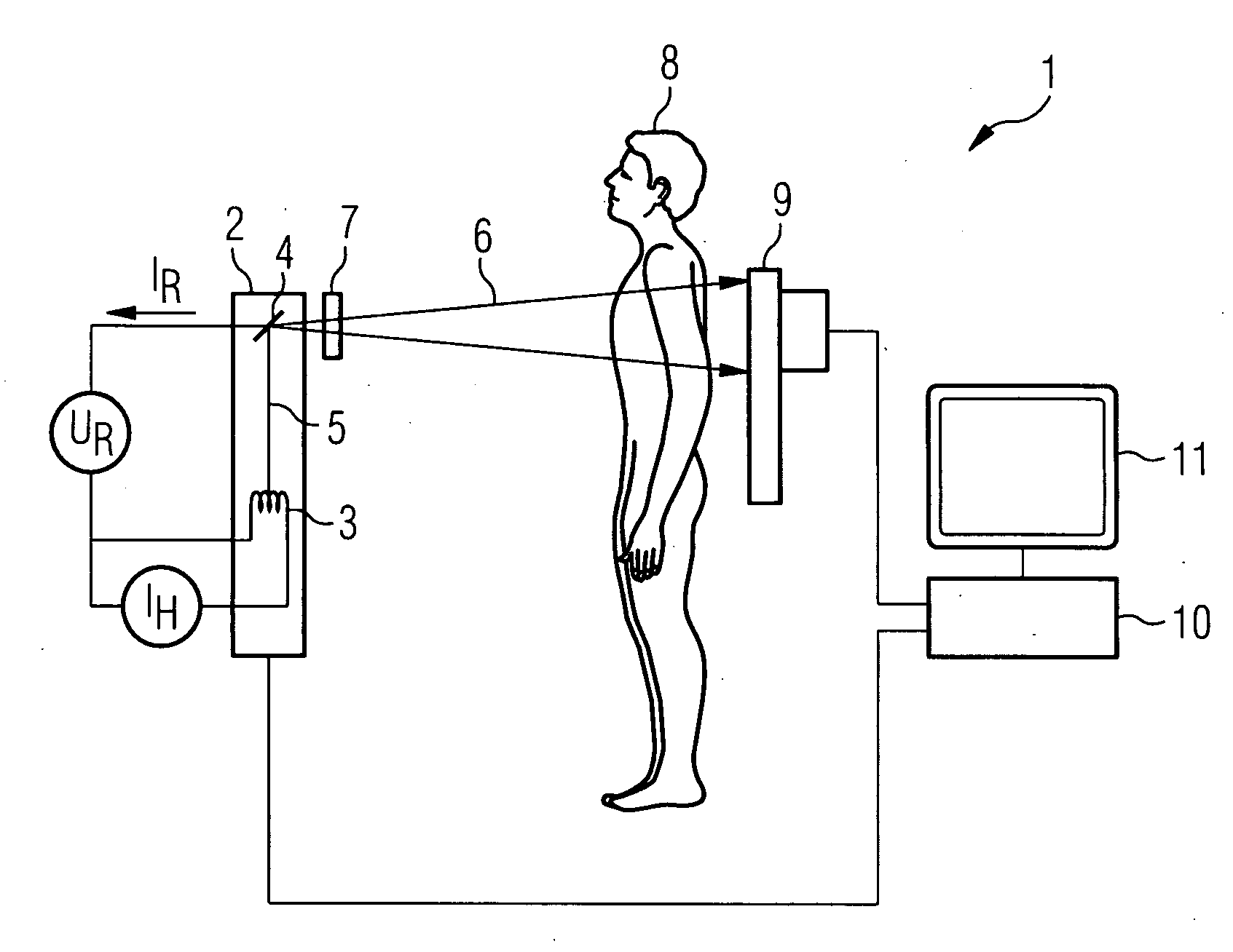
[0021]FIG. 1 shows an x-ray system 1 with which x-ray recordings for dual x-ray absorptiometry can be performed. The x-ray system 1 comprises an x-ray tube 2 having a cathode 3 in the form of an incandescent filament. The incandescent filament 3 can be heated with the aid of a heater current IH. The cathode 3 emits electrons that are accelerated in the direction of an anode 4 with the aid of a tube voltage UR. That produces an electron beam 5 that strikes the anode 4 in a focused spot. The electrons retarded in the anode 4 produce x-radiation 6, which first passes through a preliminary filter 7 to suppress the low-energy component. The preliminary filters 7 are as a rule copper plates that can be interposed having different thickness into the beam path of the x-radiation 6. The x-radiation 6 then penetrates a patient 8 under examination.

[0022]The x-radiation 6 that has passed through the patient 8 is recorded by an x-ray detector 9 that produces an absorption image of the patient 8,...


PUM


Abstract

In a method for performing recordings for dual absorptiometry, a high-energy radiation pulse is performed before a low-energy radiation pulse. Furthermore the high-energy radiation pulse is arranged at the end of an assigned radiation window of the detector. This temporal sequence of a high-energy radiation pulse and a low-energy radiation pulse allows the total time for performing the recordings for dual absorptiometry to be minimized.

Description

CROSS REFERENCE TO RELATED APPLICATIONS[0001]This application claims priority of German application No. 10 2006 014 624.7 filed Mar. 29, 2006, which is incorporated by reference herein in its entirety.FIELD OF THE INVENTION[0002]The invention relates to a method for recording projection images of an object under examination, with which method radiation pulses are emitted by a radiation source during radiation windows of a radiation detector in a high-energy range and a low-energy range and are recorded by the radiation detector.BACKGROUND OF THE INVENTION[0003]A method of said type is known from DE 101 95 715 T5. According to the known method first an x-ray pulse in the low-energy range and then a further x-ray pulse in the high-energy range are emitted by the x-ray source. The radiation emitted by the x-ray source in the high-energy range and in the low-energy range penetrates an object under examination and is recorded by an x-ray detector, which in turn produces projection images...

Claims


Application Information

Patent Timeline
IPC IPC(8): H05G1/60A61B6/00G01N23/00G21K1/12
CPCA61B6/00G03B42/02A61B6/405A61B6/4035
Inventor BERNHARDT, PHILIPP
Owner SIEMENS HEALTHCARE GMBH
Why Eureka
Try Eureka