Ratcheting tensioner with override

Inactive Publication Date: 2007-10-18
FORD GLOBAL TECH LLC
View PDF19 Cites 73 Cited by
  • Summary
  • Abstract
  • Description
  • Claims
  • Application Information

AI Technical Summary

Benefits of technology

[0008] In one embodiment of the present invention, the tooth geometry of the ratchet mechanism is selected so that when a sufficient axial force is applied to the tensioner piston and/or ratchet rack via chain/belt tension, a transverse force will be generated to override a biasing force acting on the ratchet mechanism to allow retraction of the piston and/or ratchet rack by at least one tooth to reduce the over-tensioning force applied to the chain/belt. The tooth geometry of a pawl and/or rack of the ratcheting mechanism may have an angle chosen to be slightly less than the self-locking friction angle to permit retraction. A spring associated with the pawl is sized to allow pawl and rack retraction under sufficiently high axial loads, but prevent rack retraction or piston collapse when hydr

Problems solved by technology

Insufficient tension or excessive tension may result in undesirable noise, belt slipping, chain jumping, or accelerated component wear.
However, over-tensioning of the chain can occur during a low temperature engine startup due to more viscous hydraulic fluid or oil and momentary high oil pressure acting on the piston, as well as higher driven component friction loading, especially when the operator revs the engine immediately after starting.
If the ratchet mechanism engages an additional tooth while the piston is hyper-extended, the ratchet mechanism will prevent any subsequent retraction or collapse and, any further increase in chain tension caused by thermal growth of engine components cannot be reduced or relieved by tensioner collapse.
This resulting sustained over-tension condition may produce undes

Method used


Image

  • Ratcheting tensioner with override
  • Ratcheting tensioner with override

Examples


Example

[0013] As those of ordinary skill in the art will understand, various features of the present invention as illustrated and described with reference to any one of the Figures may be combined with features illustrated in one or more other Figures to produce embodiments of the present invention that are not explicitly illustrated or described. The combinations of features illustrated provide representative embodiments for typical applications. However, various combinations and modifications of the features consistent with the teachings of the present invention may be desired for particular applications or implementations.

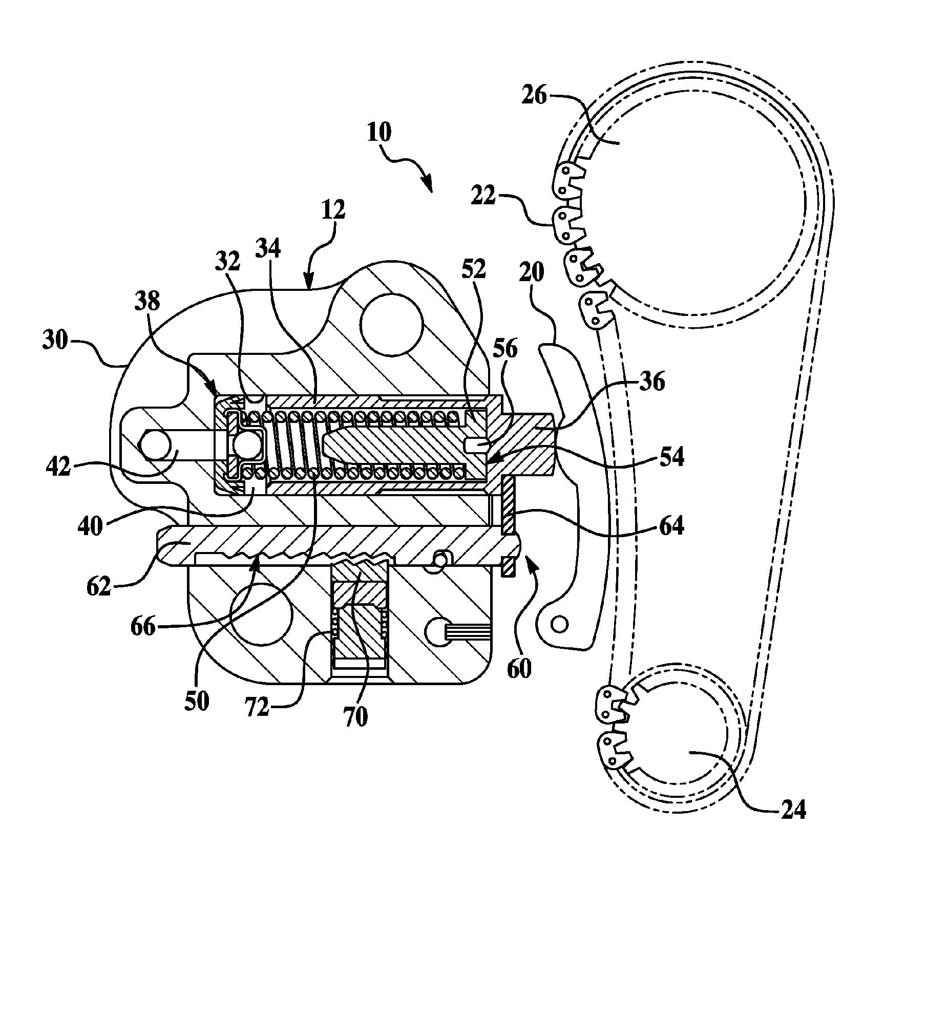
[0014] Referring now to FIG. 1, a ratcheting hydraulic tensioner having a ratchet override according to the present invention is illustrated in a representative application. As previously described, a tensioner according to the present invention may be used in a wide variety of applications to provide proper tension and control of a chain or belt in a power transmissi...


PUM


Abstract

Sustained over-tensioning of a power transmission device, such as a chain drive in an internal combustion engine, is prevented by overriding a tensioner ratchet mechanism to permit retraction of a tensioner. Tooth angle of the ratchet mechanism and pawl spring rate and preload are selected so that a sufficient axial force generated by chain/belt tension will produce a transverse force that overrides a biasing force acting on a pawl engaging a rack of the ratchet mechanism to retract a tensioning piston against hydraulic pressure and spring pressure by at least one tooth to reduce the sustained tensioning force applied to the chain/belt, while not adversely affecting the rack extension function. The tooth geometry of the pawl and/or rack of the ratcheting mechanism may have an angle chosen to be slightly less than the self-locking friction angle to permit retraction.

Description

BACKGROUND OF THE INVENTION [0001] 1. Field of the Invention [0002] The present invention relates to systems and methods for maintaining proper tension in a chain or belt using a hydraulic or mechanical tensioning system incorporating a ratcheting mechanism that reduces or prevents sustained over-tensioning by permitting bidirectional tensioner movement under certain loading conditions. [0003] 2. Background Art [0004] Internal combustion engines typically use a number of power transmission devices, such as belts and / or chains, to power or drive various engine components or accessories. Insufficient tension or excessive tension may result in undesirable noise, belt slipping, chain jumping, or accelerated component wear. A tensioner is a device that is used to provide proper tension of the chain / belt under various ambient and operating conditions and to reduce or prevent tooth jumping of a chain, or slipping of a belt, while providing damping to control drive system dynamics, as well ...

Claims


Application Information

Patent Timeline
IPC IPC(8): F16H7/08F16H7/22
CPCF16H7/0836F16H7/0848F16H2007/0859F16H2007/0853F16H2007/0806
Inventor AIMONE, MICHAEL G.
Owner FORD GLOBAL TECH LLC
Why Eureka
Try Eureka