Method of Optimum Controlled Outlet, Impingement Cooling and Sealing of a Heat Shield and a Heat Shield Element

a technology of impingement cooling and sealing, which is applied in the direction of mechanical equipment, machines/engines, light and heating apparatus, etc., can solve the problems of high brittleness of ceramic materials, limited operating temperature, and simple design, and achieve the effect of reducing the amount of compressor air extracted for cooling purposes, reducing the consumption of compressor air, and improving the power and efficiency of gas turbines

Inactive Publication Date: 2007-10-25
SIEMENS AG
View PDF15 Cites 46 Cited by
  • Summary
  • Abstract
  • Description
  • Claims
  • Application Information

AI Technical Summary

Benefits of technology

[0040] The main advantage of the invention is, that by applying the controlled outflow flow scheme the consumption of compressor air extracted for cooling purposes can be reduced by a factor of more or less 2, compared to current practices. For example in a typical conventional cooling scheme about 10% air from the compressor inlet air is required, whereas with the new cooling scheme of the invention the cooling air consumption can be significantly reduced to about 5-6%. Therefore, this directly leads to higher power and efficiency of the gas turbine, because more compressor air can be used for the combustion process.
[0041] This large potential suggests using metal heat shield elements being more ductile and forgiving than for example ceramic heat shield elements. The overall new design is simple and robust and very little changes have to be made to current conventional metal heat shields in operation. This new technology implies a high upgrade potential of the state-of-the-art.
[0042] The design procedure can be easily applied to other impingement applications as well, for instance aircraft turbine engines, other types of combustion chambers, etc.

Problems solved by technology

“Open cooling”: Here the coolant discharges into the hot gas (simple design but thermodynamically inefficient)
The disadvantage of ceramic materials is their high brittleness.
Their operating temperature is limited, however; metals must be cooled sufficiently.
The biggest drawback is the loss of combustion air and the burner bypass.
That causes a reduction of the thermodynamic efficiency and the power output of the gas turbine.

Method used


Image

  • Method of Optimum Controlled Outlet, Impingement Cooling and Sealing of a Heat Shield and a Heat Shield Element
  • Method of Optimum Controlled Outlet, Impingement Cooling and Sealing of a Heat Shield and a Heat Shield Element
  • Method of Optimum Controlled Outlet, Impingement Cooling and Sealing of a Heat Shield and a Heat Shield Element

Examples


Embodiment Construction

[0050] Identical reference indications have the same meaning in the figures.

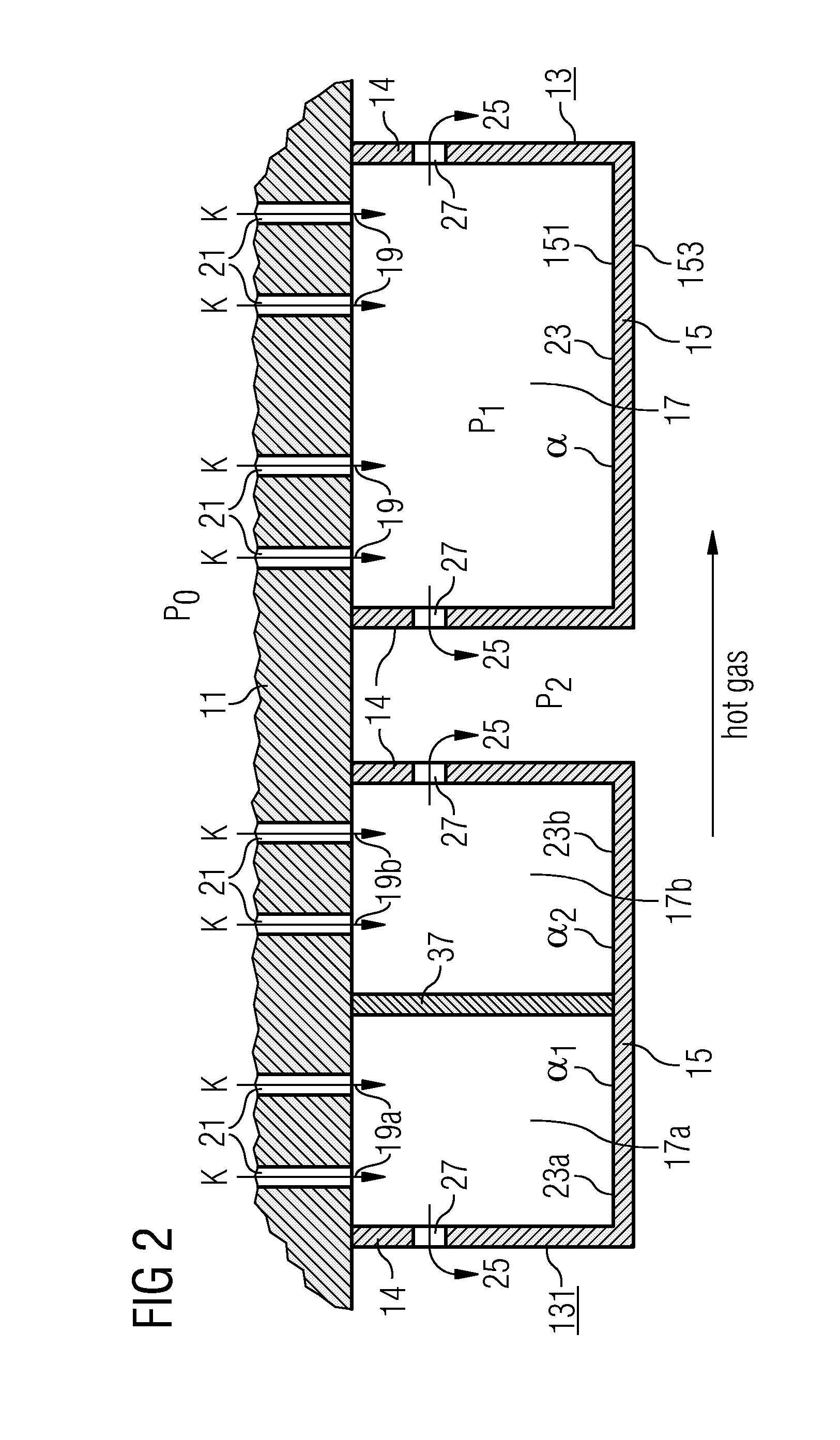
[0051] In the following an embodiment of a heat shield component in a gas turbine is depicted and explained with the accompanying drawings. The proposed designs principally do not necessarily need seals between the combustion chamber carrier wall 11 and the heat shield element 13.

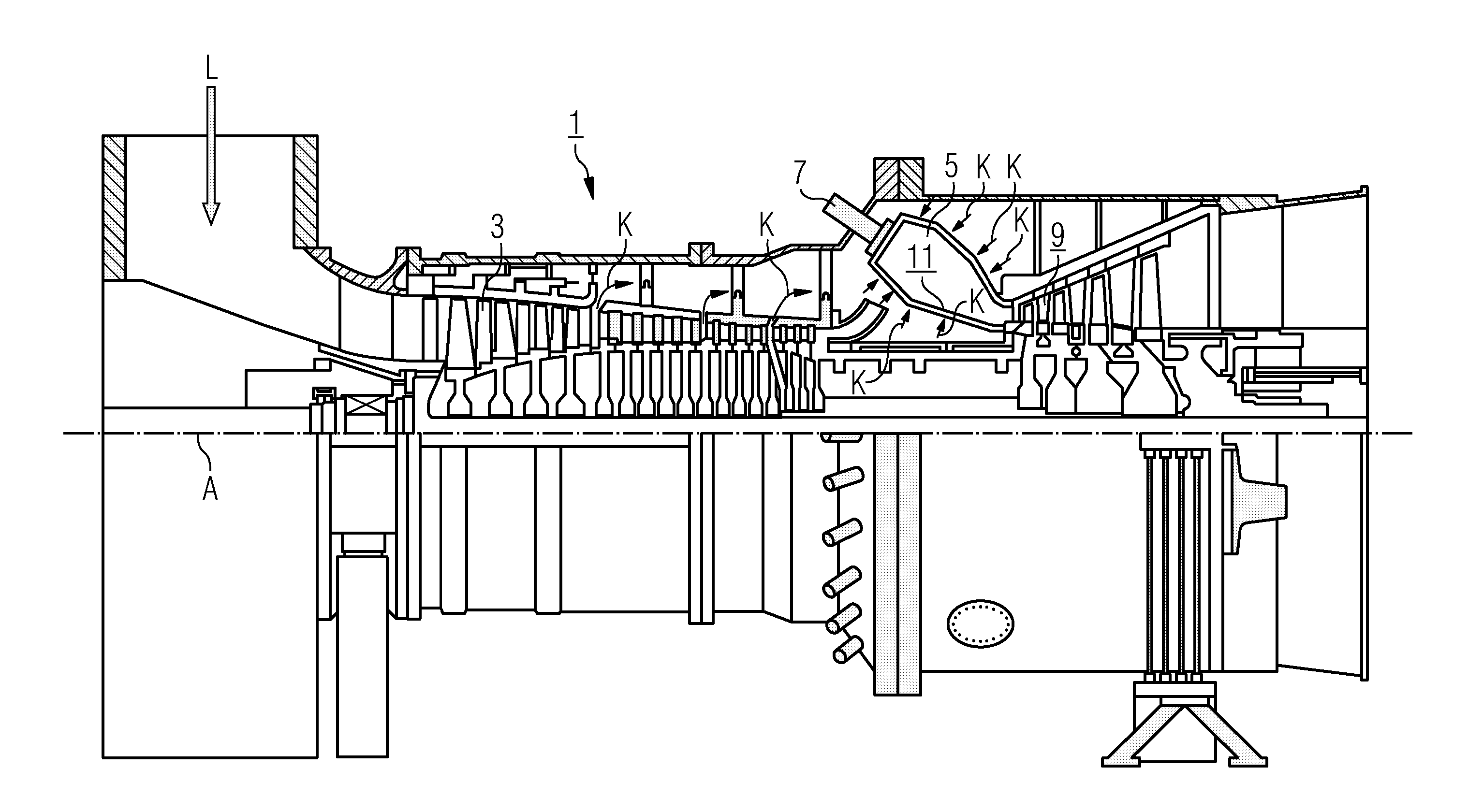
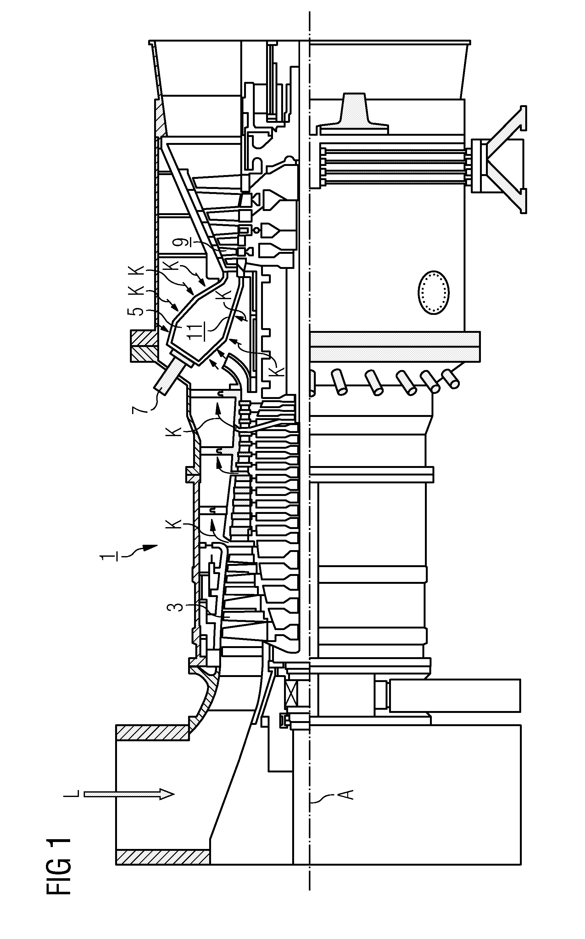
[0052] In FIG. 1 a longitudinal cross section of a gas turbine installation is presented. The gas turbine installation 1 includes a compressor 3 for combustion air, a combustion chamber 5 with a burner 7 for liquid or gaseous fuel and a turbine 9 to drive the compressor 3 and a generator which is not shown in this figure. All components are lined on a common shaft along the axis A. In the compressor 3 combustion air L is compressed. This compressed air is fed into a number of burners 7, which are arranged on a circle around the annular combustion chamber 5. Fuel, which is not shown in the drawing, is mixed with a large part of the...


PUM


Abstract

There is described a method for cooling and sealing of a heat shield element, comprising a main wall with an inner side, which is restricted by side walls or rims, and an outer side, which can be exposed to a hot fluid, and wherein a coolant is introduced into an impingement region of that heat shield element and an impingement flow of said coolant is directed on a surface area of that inner side through a plurality of impingement holes, effecting an impingement pressure drop. In the method discharge flow is metered through a number of discharge holes through said side wall or rims from the inner side to the outer side of the main wall, generating a discharge pressure drop in series with the impingement pressure drop. The impingement pressure drop and the discharge pressure drop are matched to one another so that a required coolant flow is generated which yields a required predetermined heat-transfer coefficient of the main wall. Discharging coolant into the gaps between side opposing walls of neighbouring heat shield elements only allows for an effective sealing against hot gas pingestion. Furthermore, the invention relates to a heat shield element, preferably to a single chamber or double chamber metallic heat shield element, which can be exposed to hot gases. In particular the heat shield element is suitable for being used in a combustion chamber of a gas turbine installation.

Description

CROSS REFERENCE TO RELATED APPLICATIONS [0001] This application is the US National Stage of International Application No. PCT / EP2005 / 055461, filed Oct. 21, 2005 and claims the benefit thereof. The International Application claims the benefits of European application No. 04025338 EP filed Oct. 25, 2004, both of the applications are incorporated by reference herein in their entirety.FIELD OF INVENTION [0002] The present invention relates to a method for cooling a heat shield element comprising a main wall with a cold inner side and a hot outer side, wherein a coolant is introduced into an impingement region of that heat shield element and an impingement flow of said coolant is directed on a surface area of that cold inner side through a plurality of holes for both impingement cooling and flow control. [0003] Furthermore the invention relates to a heat shield element, comprising a main wall with an inner side and an outer side, having an impingement region adjacent to the inner side, s...

Claims


Application Information

Patent Timeline
Patent Type & Authority Applications(United States)
IPC IPC(8): F23R3/00
CPCF02K1/82F23M2900/05005F23R3/002F05D2260/201F23R2900/03041F23R2900/03044Y02T50/675F23R3/005Y02T50/60
Inventor DAHLKE, STEFANGRUSCHKA, UWEHEILOS, ANDREASLIEBE, ROLAND
Owner SIEMENS AG
Why Eureka
Try Eureka