

Electric power steering apparatus
a technology of electric power steering and steering wheel, which is applied in the direction of electrical steering, mechanical energy handling, transportation and packaging, etc., can solve the problems of increased number of components, high cost, and large size of the apparatus
- Summary
- Abstract
- Description
- Claims
- Application Information
AI Technical Summary
Benefits of technology
Problems solved by technology
Method used
Image

Examples
embodiment 1
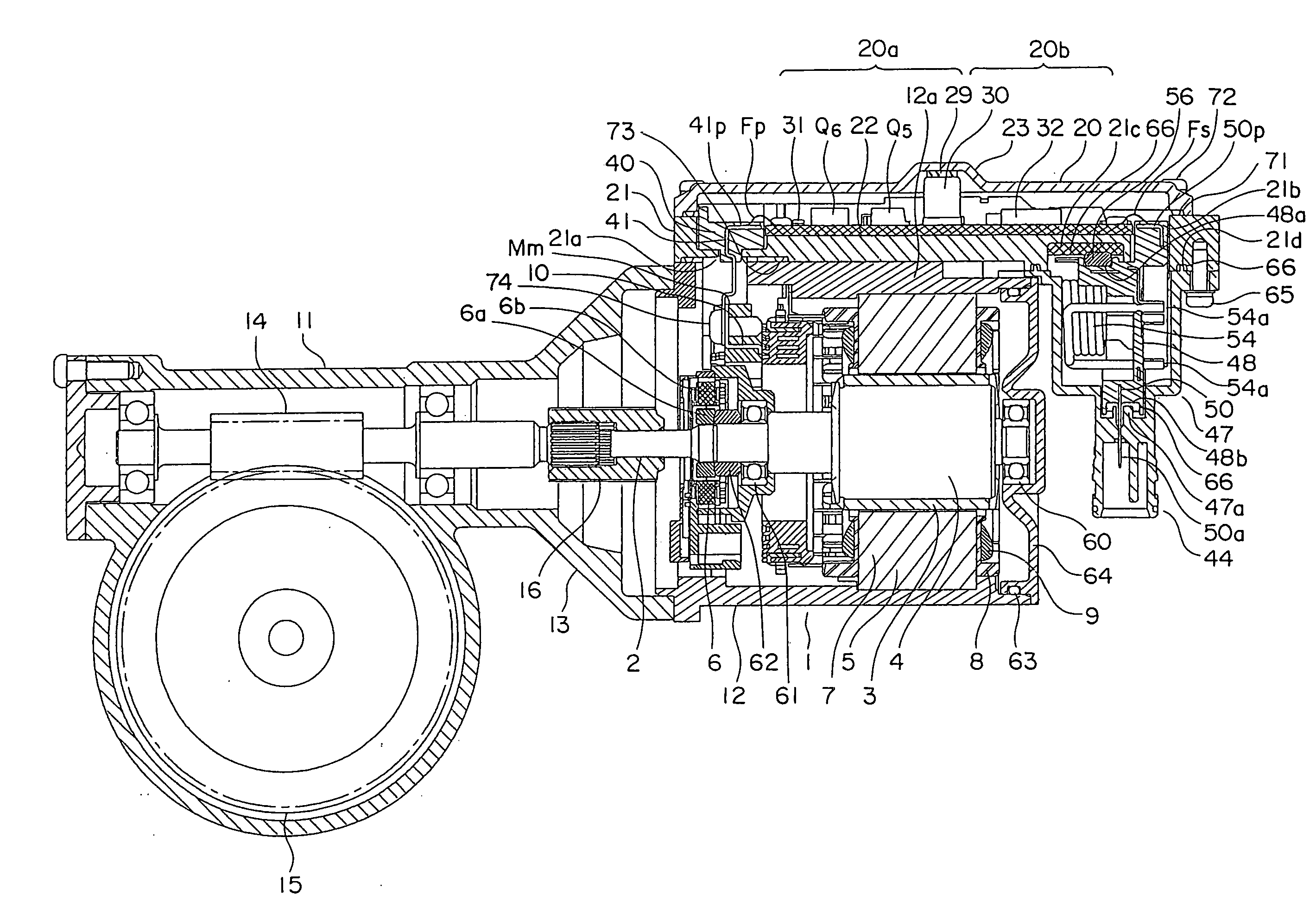
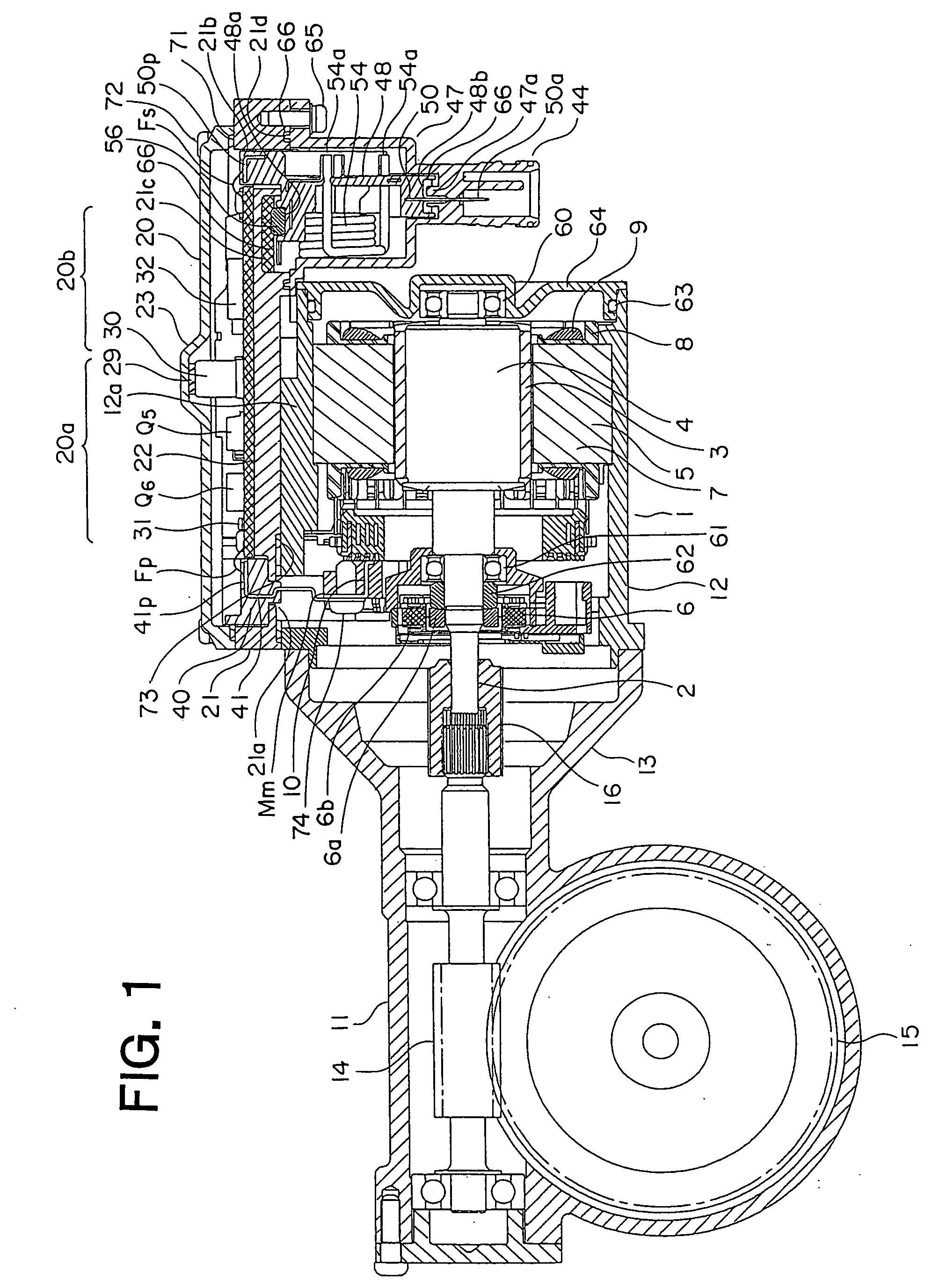
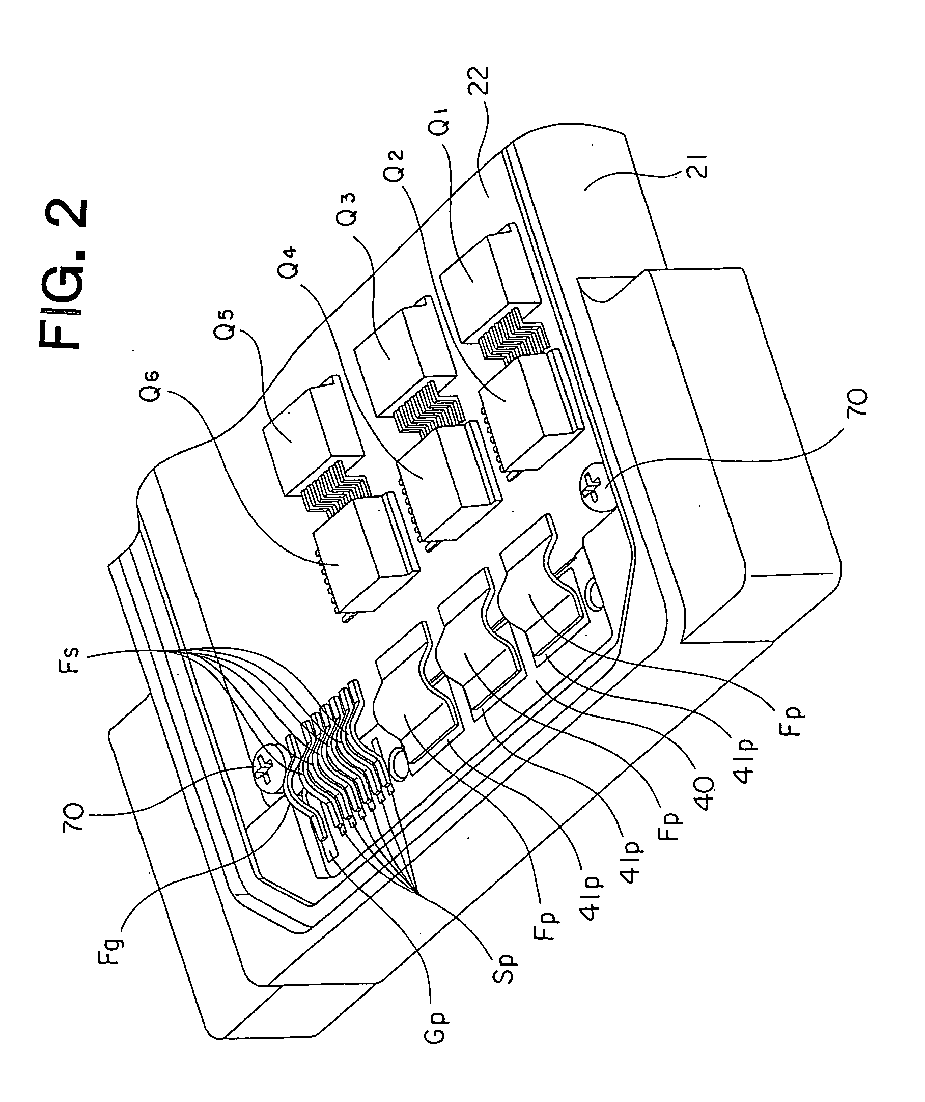
[0019]FIG. 1 is a cross sectional view that shows an electric power steering apparatus according to a first embodiment of the present invention, and FIG. 2 is a perspective view that shows a part of the interior of the electric power steering apparatus in FIG. 1.
[0020]In these figures, an electric motor 1 in the form of a three-phase blushless motor of this electric power steering apparatus is provided with an output shaft 2, a rotor 4 with a permanent magnet 3 having eight magnetic poles fixedly attached to the output shaft 2, a stator 5 arranged around the rotor 4, and a rotational position sensor 6 arranged at an output side of the output shaft 2 for detecting the rotational position of the rotor 4.
[0021]The stator 5 has twelve salient poles 7 arranged in opposition to the outer periphery of the permanent magnet 3, insulators 8 attached to these salient poles 7, respectively, and armature windings 9 wound around the insulator 8 and connected with three-phases U, V and W. The arma...
embodiment 2
[0096]FIG. 4 is a cross sectional view that shows part of the interior of an electric power steering apparatus according to a second embodiment of the present invention, and FIG. 5 is a cross sectional view of essential portions of a control unit 20 of FIG. 4.
[0097]In this embodiment, metal elements Fp, Fs, Fg are arranged in a side by side relation and mounted on one side surface of an insulation sheet 81 having flexibility and high thermal conductivity. Specifically, three power metal elements Fp for large current are mounted on the insulation sheet 81 for supplying motor current to armature windings 9 of three phases U, V and W of an electric motor 1 via motor terminals Mm. Also, six signal metal elements Fs are mounted on the insulation sheet 81 for sending a signal from a rotational position sensor 6 of the electric motor 1 to a microcomputer 32 on the metal substrate 20 via sensor terminals (not shown). Further, one ground metal element Fg is also mounted on the insulation she...
PUM
 Abstract
Description
Claims
Application Information