Electrochemical Machining Tool and Method for Machining a Product Using the Same

a technology of electrochemical machining and product, applied in the direction of manufacturing tools, electrical-based machining electrodes, sliding contact bearings, etc., can solve the problem of not being able to describe the machining of an axial dynamic pressure generating groove at a designated position on the edge of the sleeve, and achieve the effect of reducing the number of individual process steps, not reducing precision, and reducing cos

Inactive Publication Date: 2007-10-25
MINEBEA CO LTD
View PDF3 Cites 18 Cited by
  • Summary
  • Abstract
  • Description
  • Claims
  • Application Information

AI Technical Summary

Benefits of technology

[0019] The electrode body of the electrochemical machining tool of the present invention, and the ECM methods described herein can produce a sleeve. The sleeve is manufactured, for example, from a piece of metal stock by electrochemical machining using the electrochemical machining tool of the present invention. Alternatively, the sleeve can further embody a hydrodynamic pressure bearing having the above described sleeve for use in a spindle motor, such as a hard disk spindle motor.
[0020] The electrochemical machining tool and electrochemical machining method of the present invention allow axial dynamic pressure generating groove machining at a designated position of the edge of the workpiece, radial dynamic pressure generating groove machining at a designated position of the inner surface of the workpiece, and deburring machining of the oil pool on the inner surface of the workpiece to be conducted simultaneously as a single process while the positions of the workpiece and machining electrodes are set only once. Depending on the individual instanc

Problems solved by technology

However, while the above discussed reference generally describes machining of a radial dynamic pressure generating groove on the inner circumfere

Method used


Image

  • Electrochemical Machining Tool and Method for Machining a Product Using the Same
  • Electrochemical Machining Tool and Method for Machining a Product Using the Same
  • Electrochemical Machining Tool and Method for Machining a Product Using the Same

Examples


first embodiment

[0049] In accordance with a first embodiment, radial dynamic pressure generating groove electrochemical machining, axial dynamic pressure generating groove electrochemical machining and electrochemical machining for deburring are carried out simultaneously using the electrochemical machining tool 1 of the present invention.

[0050] It will be appreciated that the oil pool 41 is formed by a mechanical machining process. The sleeve 4, which as noted is formed from a blank machined austenitic stainless alloy, will be electrochemically machined using the electrochemical machining tool 1 of the present invention.

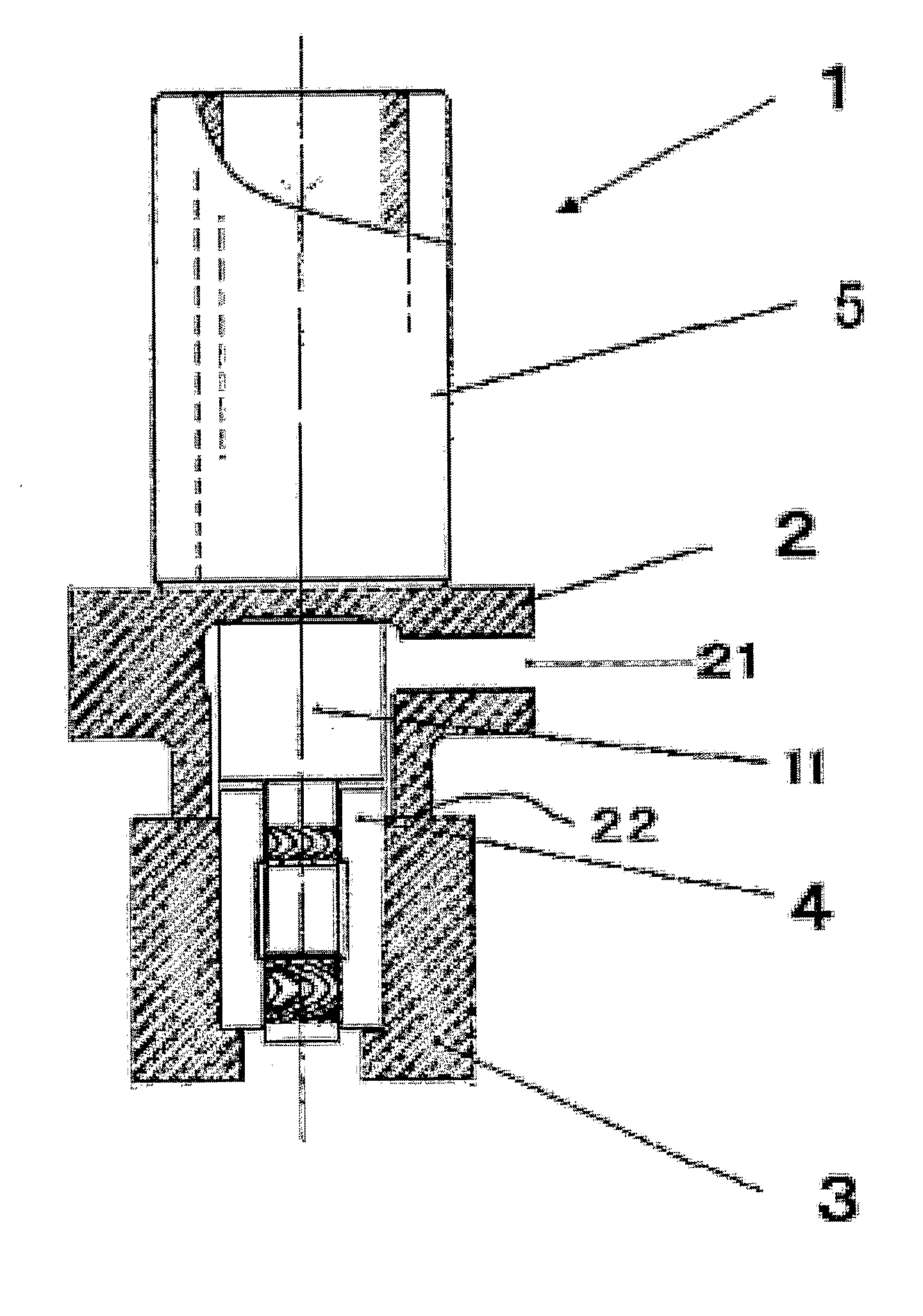
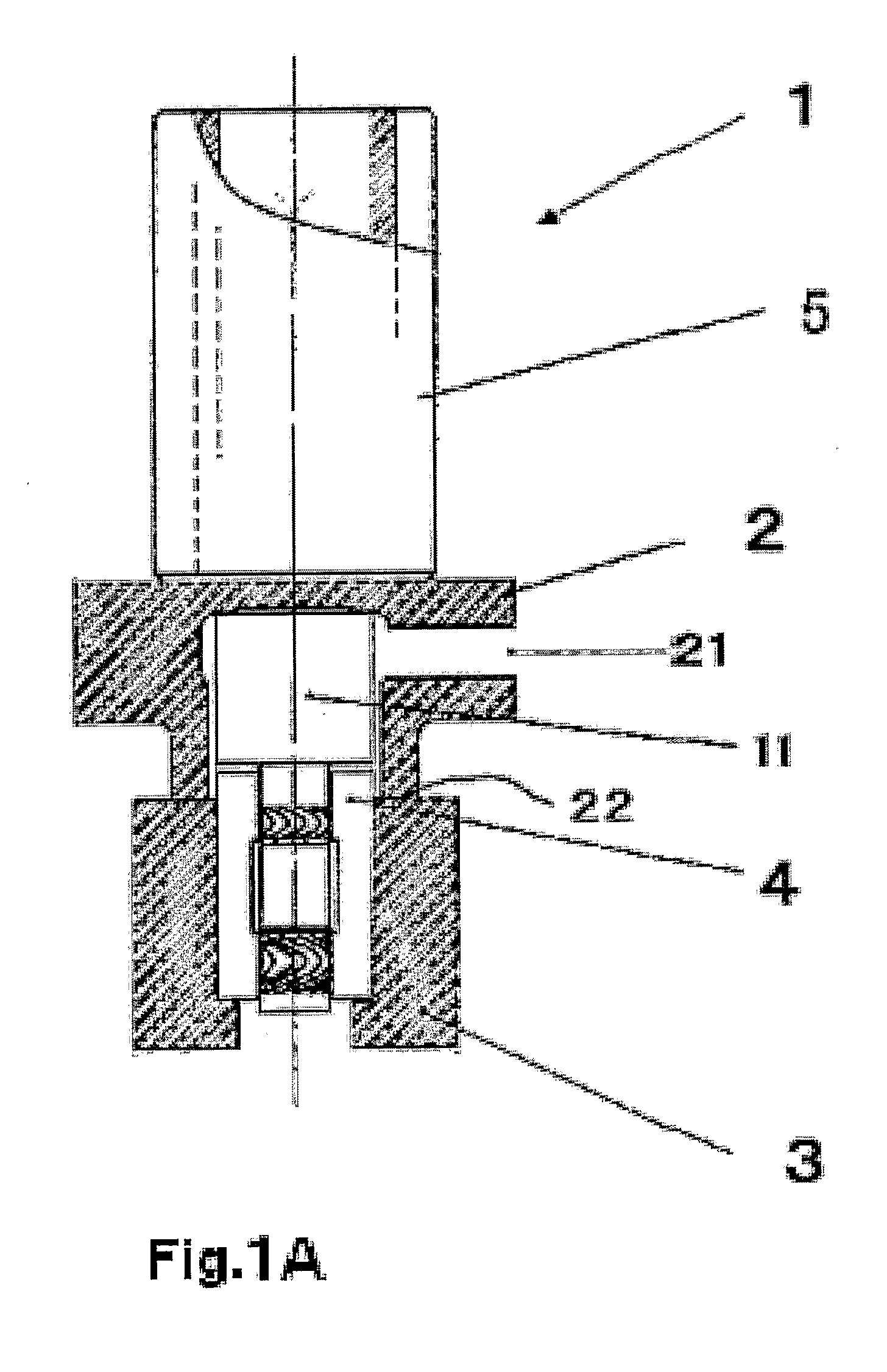
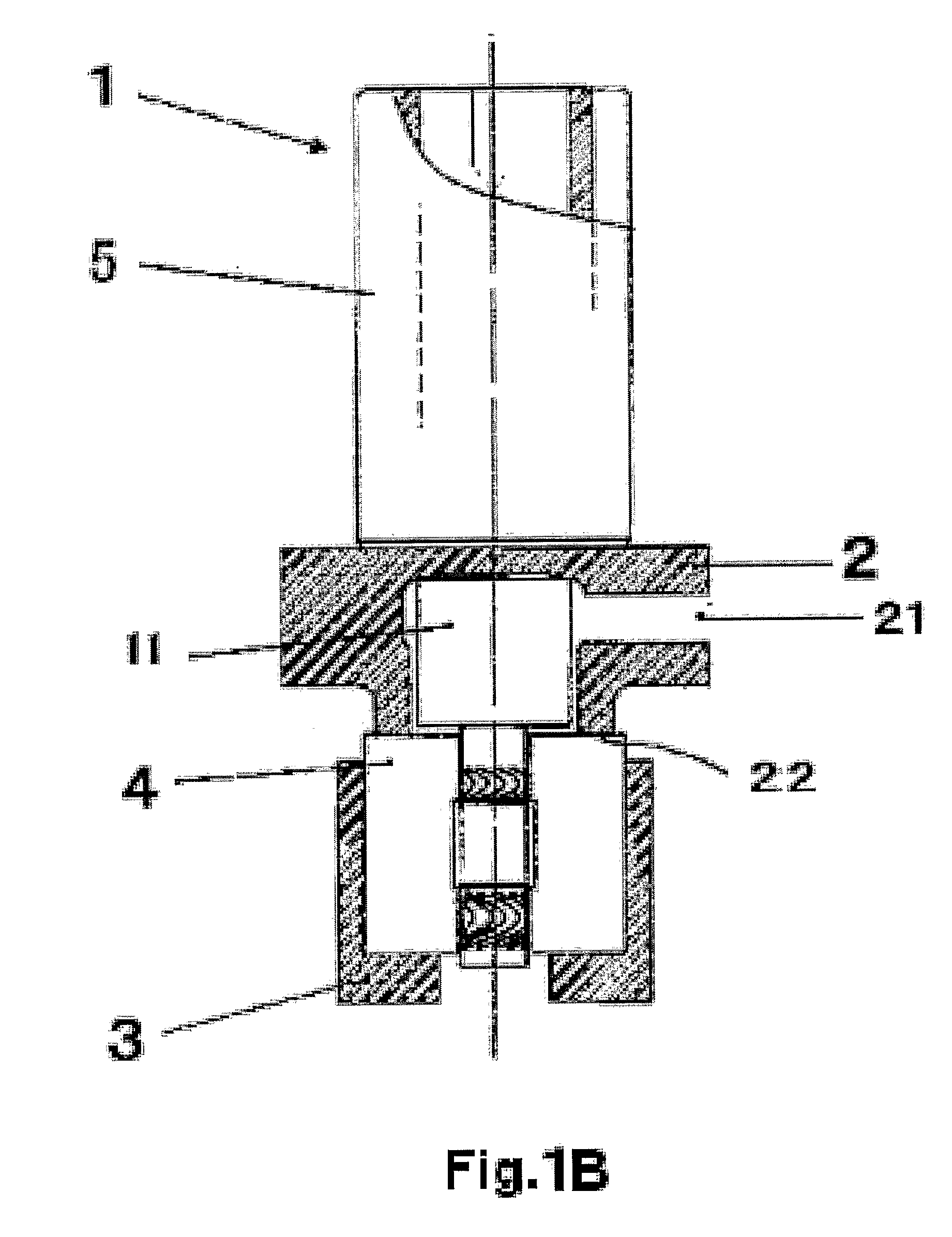
[0051] As shown in FIG. 2, the electrochemical machining tool 1 of the present invention includes the insulated guiding tool 2 and the electrode body 11. The electrode body 11 includes the machining electrode 13 located on the large diameter portion thereof and configured to form an axial dynamic pressure generating groove on the edge of the sleeve 4, the machining electrode 12 lo...

second embodiment

[0061] In accordance with a second embodiment, axial dynamic pressure generating groove electrochemical machining and deburring are carried out simultaneously, and radial dynamic pressure generating groove electrochemical machining is carried out separately.

[0062] As shown in FIG. 4, the oil pool 41 is formed by mechanical machining such as a turning process using a machine tool, a mill, a lathe, or the like, to prepare the sleeve 4, which is made of, for example, austenitic stainless steel. The electrochemical machining tool 1, as shown for example in FIG. 3, the insulated guiding tool 2 and the supporting tool 3, which holds or supports the sleeve 4, are placed or set at a predetermined or designated position. The sleeve 4 is contained in the concave supporting portion of the supporting tool 3. The electrochemical machining tool 1 is then lowered, and, with a certain amount of force, the edge of the projecting portion 22 of the insulated guiding tool 2 is pushed against the edge o...

third embodiment

[0070] In accordance with a third embodiment, an electrochemical machining tool of the present invention simultaneously performs an electrochemical machining process for forming a radial dynamic pressure generating groove and an electrochemical machining process for removing burrs occurring from a mechanical machining process. An electrochemical machining process for forming an axial dynamic pressure generating groove is performed separately.

[0071] The electrochemical machining tool 1 of the present embodiment corresponds to the electrochemical machining tool 1 as shown, for example, in FIG. 2, with the electrode 13, for machining an axial dynamic pressure generating groove, omitted. In other words, the electrochemical machining tool 1 has the electrode body 11 on a front end or edge thereof. The electrode body 11 includes the radial dynamic pressure generating groove machining electrode 12, and the deburring electrode 14. A drive control circuit (not shown) intervenes between the e...


PUM

PropertyMeasurementUnit
Pressureaaaaaaaaaa
Flow rateaaaaaaaaaa
Electrochemical propertiesaaaaaaaaaa

Abstract

An electrochemical machining tool (1) for electrochemical machining includes an electrode body (11). The electrochemical machining tool (1) and associated method can conduct simultaneous electrochemical machining of at least two of a radial dynamic pressure generating groove (43), an axial dynamic pressure generating groove (44), and a removal of a burr (42) associated with an oil pool (41). Electrochemical machining is performed with groove machining electrodes (12, 13) and deburring electrodes (14). A sleeve (4) machined using the electrochemical machining tool (1) and associated method has the radial dynamic pressure generating groove (43), the axial dynamic pressure generating groove (44), and the deburred oil pool (41). The sleeve (4) can be used in a hydrodynamic pressure bearing for use in a spindle motor of a hard disk drive.

Description

CROSS REFERENCE TO RELATED APPLICATION [0001] This application is based on and incorporates by reference Japanese Patent Application No. 2004-272505, which was filed on Sep. 17, 2004 and Japanese Patent Application No. 2005-207881, which was filed on Jul. 15, 2005. BACKGROUND OF THE INVENTION [0002] The present invention relates to electrochemical machining (ECM), and more specifically to an electrochemical machining tool and a method of machining using the electrochemical machining tool for manufacturing a high quality product, such as a bearing sleeve, at a low cost. [0003] Conventional electrochemical machining equipment for deburring, as described, for example, in Japanese Unexamined Patent Application H10-277842, includes electrodes and a pulse current supply with a direct current power supply and a control device for applying a pulse current to a workpiece and to the electrodes. The electrodes include machining electrodes for deburring the workpiece and electrodes for detectin...

Claims


Application Information

Patent Timeline
IPC IPC(8): B23H3/04
CPCB23H3/04B23H2200/10B23H9/00F16C17/107F16C33/107F16C33/14
Inventor OBARA, RIKUROYASUDA, TOMOYUKI
Owner MINEBEA CO LTD
Why Eureka
Try Eureka